Full-Scale Demonstration Shows Breakthrough in GT NOx and CO Removal Using Patent-Pending EnergyLink Direct Injection of Liquid Ammonia
In the U.S., most industrial and utility-scale gas turbines must be purchased with selective catalytic reduction (SCR) technology to achieve NOx permit levels between 2.0 to 2.5 parts per million volume, dry - ppmvdc. The combustion of natural gas, hydrogen, or fuel oil generates carbon monoxide (CO) and various nitrogen oxides (NOx), which are toxic to the environment and smog-forming. Ammonia is used as the reagent to remove these toxins, reacting with the NOx and CO molecules over a catalyst, usually made from a base metal such a titanium or vanadium.
EnergyLink International specializes in “hot” SCR systems (i.e., SCRs attached to gas turbines used in a simple cycle). These systems present a particular challenge due to the extremely high temperatures and velocities of the GT exhaust streams. The ideal temperature for catalyst bed performance is 800 to 900 °F. Gas turbine exhaust is hot, reaching up to 800 to 900 °F for smaller industrial turbines but approximately 1,200 °F or higher for large central station utility machines and aero-derivative turbines.
Compliance with NOx (nitrogen oxide) and ammonia leakage emissions regulations is crucial for gas-fired turbines in power generation. These regulations mandate achieving 2.0 to 2.5 parts per million stack NOx, and carbon monoxide (CO) limits of 1.0 to 6.0 ppm.The levels of NOx in the exhaust gas from a gas turbine operating in simple cycle can range from 10 to 400 ppm, depending on the fuel and combustion system used. Regulations also limit the amount of unreacted ammonia byproduct (called ammonia slip) to around 10 ppmvdc or lower.
Gas turbines, used for renewable energy backup and behind-the-fence power generation, parallel the growth in electricity demand (Fig. 1). Catalysts for the load upswing in the U.S. include investments in dispatchable backup power to support renewable energy and behind-the-fence generation to fill electricity demand from Artificial Intelligence (AI), and the Inflation Reduction Act’s boost to manufacturing and infrastructure.
The energy and utilities sector (E&U) in the U.S. deploys approximately 1,000 peaker plants, mostly gas-fired aero-derivatives. Another 38 Gigawatts (GW) of peak demand additions are projected over the next five years. To meet this demand, Georgia, North Carolina, South Carolina, Virginia, Tennessee, and Texas, among other states, propose building multiple gas-fired peaker plants1. In conjunction, an estimated 290 TWh of electricity will be needed in 2030 to meet demand just from data centers and EVs, on top of which is an additional 9 percent rise in demand from industry. Some of this electrical growth will need to be supported by gas-fired generation, whether as peakers or islanded power2. All these new gas-fired units operating in simple cycle will need hot SCR technology.


Source: Cited in Brad Plumer and Nadja Popovich. “A New Surge in Power Use is Threatening U.S. Climate Goals,” The New York Times, March 14, 2024.

EnergyLink has installed a full-sized SCR system behind an LM6000PC gas turbine. This SCR was outfitted with a “conventional” ammonia injection grid (Fig. 2) and EnergyLink’s Direct Injection system test unit (Fig. 3).The Direct Injection system test unit reduced NOx from 25 ppmvdc to 2.5 ppmvdc while maintaining ammonia slip below 5 ppmvdc. The SCR system used 19% aqueous ammonia as the reducing reagent. EnergyLink has filed patent applications for its Direct Injection system.


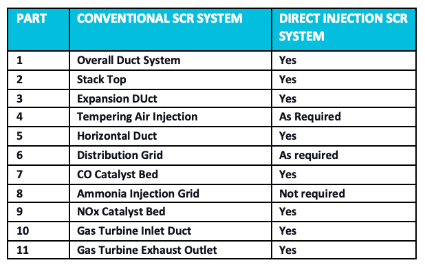
Overall Duct System – 1; Exhaust Stack – 2; Expansion Duct – 3; Tempering Air Injection System – 4; Horizontal Duct – 5;Distribution Grid – 6; CO Catalyst Bed – 7; Ammonia Injection Grid – 8; NOx Catalyst Bed – 9; Gas Turbine Inlet Duct – 10; Gas Turbine Exhaust Outlet – 11.


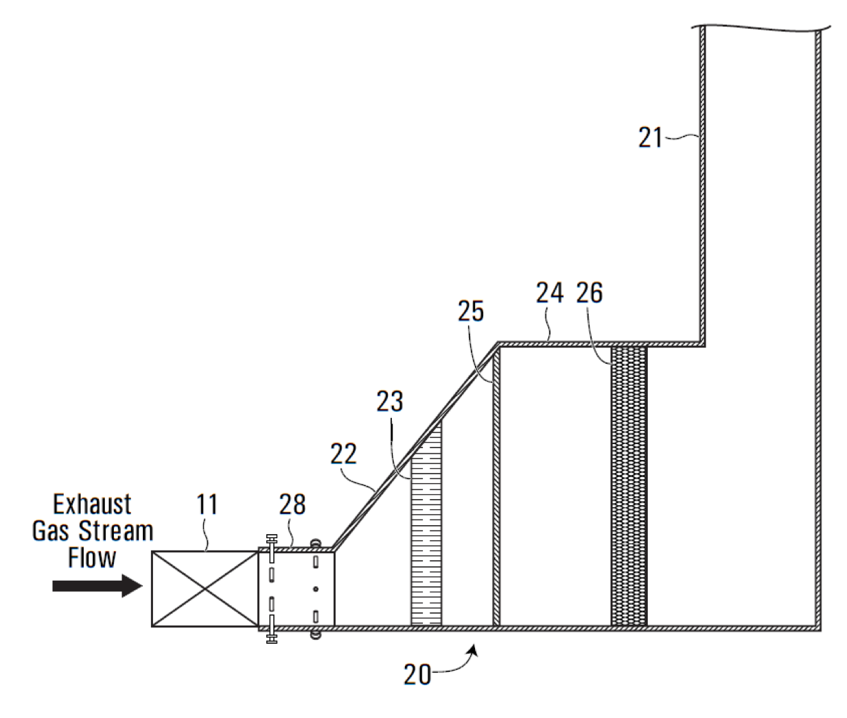
Overall Duct System – 20; Exhaust Stack – 21; Expansion Duct – 22; Tempering Air Injection System – 23; Horizontal Duct – 24; Distribution Grid – 25; CO/NOx Combination Catalyst Bed – 26; Gas Turbine Inlet Duct – 11; Direct Injection Duct – 28.
In the Conventional SCR system, ammonia is vaporized using an electric heater or recirculated exhaust gas in an external ammonia vaporization skid (AVS), and enters the turbine exhaust through the ammonia injection grid (AIG).Several hundred conventional SCR systems have been installed worldwide over 20 to 30 years.
In EnergyLink’s Direct Injection system, liquid ammonia is injected into the turbine exhaust stream using multiple retractable air-cooled injection nozzles at the Direct Injection Duct (Fig.3, 28), so that the radial distance from the casing and the axial distance from the turbine can be varied.The conventional AVS and AIG were installed as backups and were not used during the direct injection system tests.A dual SCR/CO catalyst (Fig. 3, 26) was used in EnergyLink’s Direct Injection system, which, according to EnergyLink’s knowledge, is the first dual catalyst installation of its kind in the world.
Data was gathered from the EnergyLink Direct Injection system demonstration unit running under full load, 50% load, and 25% load. Multi-point traverse testing of the system was performed to measure NOx (NO and NO2), ammonia, CO, temperature, and oxygen at the exit of the SCR catalyst.
In this testing, EnergyLink’s Direct Injection system removed nitrogen oxide (NOx) and carbon monoxide (CO) molecules from a full-load exhaust gas stream better than the conventional SCR design using a conventional ammonia grid. In SCR catalyst bed design, the exhaust gas stream residence time within the catalyst bed is proportional to NOx removal. When a gas turbine operates at full load, the exhaust gas velocity is the highest, resulting in the shortest residence times within the catalyst bed. Full load conditions govern the catalyst bed designs, including the thickness of the catalyst bed, to ensure that exhaust gas has sufficient residence time for the required NOx removal.
EnergyLink’s Direct Injection system injects the reducing agent into the exhaust gas stream as a liquid rather than a heated gas right at the Turbine Exhaust Gas Inlet Duct entrance (Fig. 3, 28). Cooling air and reducing agent liquids are fed into injectors via separate supply lines. This configuration contrasts with a conventional SCR system, where the exhaust gas stream must travel through the inlet duct to reduce its velocity and also be cooled within the expansion duct to produce a temperature ideal for catalyst bed(s) performance -800 to 900 °F.
In systems with an exhaust gas stream at temperatures higher than 900 °F, introducing cooled air as a mixture of ambient air and exhaust gas via a tempering air injection system reduces the exhaust gas stream temperature to an effective range. After reducing the velocity and, if necessary, the temperature of the exhaust gas stream, the stream passes through a distribution grid at or near the entrance of the horizontal duct. The distribution grid spreads the flow of the exhaust gas stream evenly across the cross-section of the horizontal duct.
In EnergyLink’s Direct Injection system, components such as the reducing agent vaporization system, heaters, blowers, ducting, injection grid, and associated pipes and valves are unnecessary (Fig. 5). Reducing these components and the footprint of the SCR system will result in a material reduction in capital and installation costs.Without a large ammonia vaporization fan, parasitic loads and operating costs are also reduced.


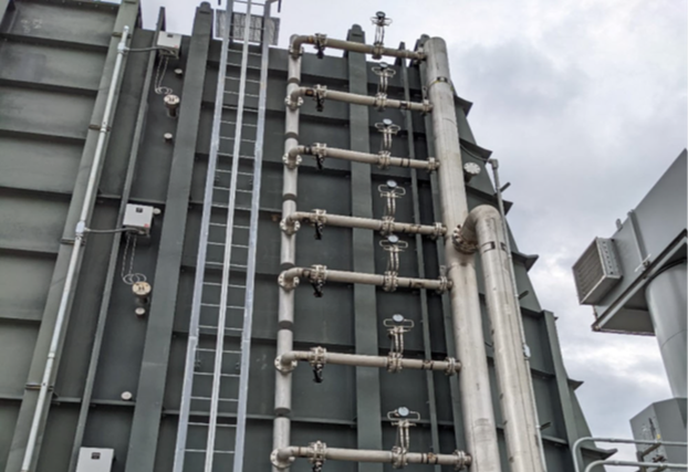
Note:The Ammonia Vaporization Skid (AVS) for Direct Injection is significantly reduced without a vaporization fan and associated ducting.
One of the features of EnergyLink’s Direct Injection system is the ability to inject liquid ammonia at multiple locations and various radial distances in the highly turbulent circular duct to achieve NOx and CO comparable to or better than the conventional SCR system.EnergyLink’s Direct Injection system replaces the ammonia injection grid and its many valves and control devices with a pared-downed system of injection lances and custom-designed nozzles easily adjustable in depth and precisely positioned to obtain the best % root-mean-square (RMS) distribution (Side Panel %RMS explained).


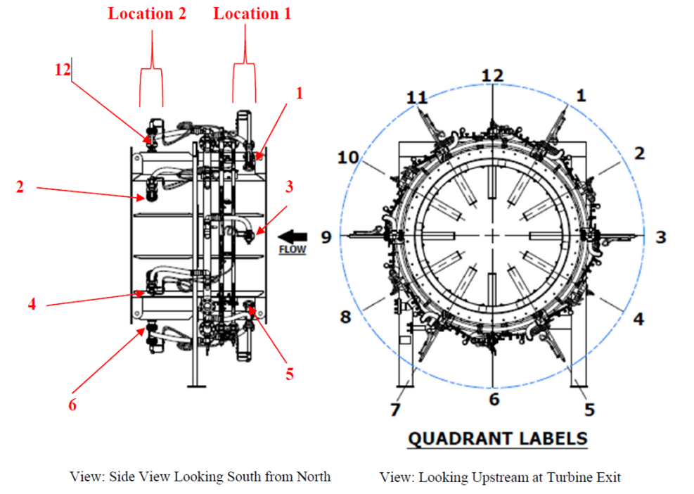
In the full-scale Direct Injection system, two (2) sets of six injection lances are spaced around the circumference of the inlet duct, designated Location 1 (upstream) and Location 2 (downstream) (Fig. 6).
At each location, lances are spaced 60 degrees apart. Between Locations 1 and 2, lances are
staggered 30 degrees apart, forming a wall clock pattern when looking down the circular duct. Lances are numbered accordingly, with the lance on the top being Lance #12, and the lance on the bottom being Lance #6. Location 1 has odd-numbered lances, and Location 2 has even-numbered lances (Fig. 6).


Direct injection “tuning” is performed by adjusting the number and location of lances in use, ammonia flow rates to the lances, and lance positions (fully inserted, half extended, fully extended, or any position in between) to settle on a configuration that results in the best SCR system performance and ammonia-to-NOx distribution.
Test results from EnergyLink’s full-scale Direct Injection system successfully achieved 2.5 ppmvdc and 90% NOx reduction, yielding an RMS for ammonia-to-NOx distribution of 5.3% (Fig. 7).This result was confirmed by both physical flow and computation fluid dynamics (CFD) models.The conventional Ammonia Injection Grid (AIG) attained approximately 10.0% RMS for ammonia-to-NOx distribution.With its lower RMS values, EnergyLink’s Direct Injection SCR system has higher NOx removal at a given ammonia slip or, alternatively, can achieve lower ammonia slip at a given NOx removal level than a conventional SCR system. The EnergyLink Direct Injection system achieved the required exit NOx, CO and ammonia slip levels at all operating loads.


To interpret the graph, find the percent NOx conversion and the "Ammonia to NOx" RMS distribution, then read the expected ammonia slip at the left. For example at 90% NOx conversion, the Direct Injection "Ammonia to NOx" RMS distribution is approximately 5.3% which correlates to an ammonia slip of approximately 1.5 ppmv. At 90% NOx conversion, the Conventional AIG "Ammonia to NOx" RMS distribution is approximately 10% which correlates to an ammonia slip of approximately 3.0 ppmv.

EnergyLink has also verified that its Direct Injection system can be applied to all aero-derivative gas turbine models. The company has tested its Direct Injection design for various gas turbine models with varying gas turbine exhaust velocities using one-eighth-scale physical flow models and computational fluid dynamics for all General Electric, Solar, Baker Hughes, and Siemens aero-derivative gas turbines, yielding similar successful results.In addition, Direct Injection is also applicable to all large-frame turbines as their higher exhaust stream velocities are highly conducive to EnergyLink’s SCR methodology.
Conclusion
Full-scale testing and modeling results show EnergyLink’s patent-pending Direct Injection SCR system generates a significantly better RMS for ammonia-to-NOx distribution than conventional SCR systems. The improved %RMS translates into higher NOx and CO removal levels with considerably lower amounts of ammonia slippage.
Other benefits of the EnergyLink Direct Injection system are:
- A significantly lower capital cost compared to a conventional SCR system;
- Reduced footprint with reduced duct sizes;
- Simplified AVS for additional cost savings;
- A significantly lower parasitic load compared to a conventional system from the elimination of ammonia vaporization fans;
- Lower installation time and cost; and,
- Wide application of Direct Injection across all gas turbine models.
References
1 Brad Plumer and Nadja Popovich. (March 14, 2024). A New Surge in Power Use is Threatening U.S. Climate Goals, The New York Times (https://www.nytimes.com/interactive/2024/03/13/climate/electric-power-climate-change.html).
2 Paul Ciampoli, American Public Power Association. (July 1, 2024). Data Centers EV Expansion Create Around 300 TWh Increase in U.S. Electricity Demand by 2030 (https://www.publicpower.org/periodical/article/data-centers-ev-expansion-create-around-300-twh-increase-us-electricity-demand-2030).

