The catastrophic effect of choke in axial compressors and prevention measures
BY LEYDEN LOPEZ

Axial compressors are used in large-scale processes where a significant amount of gas is required at a relatively low pressure. Typical applications are at the oil refinery’s fluid catalytic cracking unit (FCCU) as the main air blower, at the steel-mill as the blower for the blast furnace or as part of an industrial or aeroderivative gas turbine. Centrifugal compressors are more commonly used due to their versatility: they can compress a wide range of flows to a high discharge pressure. The stable operation of axial and centrifugal compressors is limited by surge and choke. Surge is a violent flow reversal that occurs when the process restricts the compressor flow below a certain minimum value.
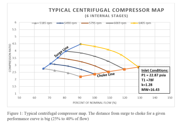
Choke occurs when the process does not create enough restriction to the compressor flow and the compressor operates at its maximum flow for a given performance level. Control systems are available to protect the compressor from surge, but not always from choke. Investigation of several catastrophic failures using diagnostics tools point to choke (not surge) as the root cause of the failure due to fatigue of a rotating blade or fixed vane. Operation in deep choke, especially of axial compressors during unloaded operation, therefore, should be avoided. The effect of choke in centrifugal compressors is generally overlooked and is typically of no major concern. This is in great part due to the natural shape of the performance curve that represents a significant change in flow from the limit of surge to the limit of choke (Figure 1).

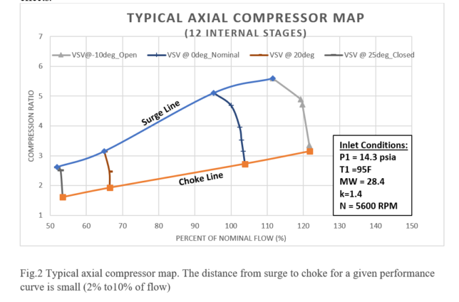
In axial compressors, however, this distance is significantly less (Figure 2). The more stages a compressor has, the higher the pressure ratio but the smaller the operational margin between surge and choke regions. Figure 2 shows the performance curves of a 12-stage axial compressor. The operational margin of a performance curve is significantly less than the one of a 6-stage centrifugal compressor shown in Figure 1.
OEMs are not always clear about the precise location of the choke line as most attention is given to the surge line. The same mistake is transferred to control systems, which focus exclusively on protection from surge. However, ignoring the effect of choke in axial compressors has cost refinery owners months of production loss due to the catastrophic failure of the axial main air blower (MAB), one the most critical pieces of machinery in the refinery. Compressor choke or stonewall is an unstable operating condition, which occurs when the compressor is operating at low discharge pressure and high f low rate. This leads to increased gas velocity in the compressor.
The increase in gas velocity occurs until it reaches sonic velocity or resonance at the blade throat (Mach 1). At this point, no more flow can pass through the compressor, causing high frequency and low amplitude vibration of the rotor blades or stator vanes. During choke, the flow channels between blade rows may experience blockage effects.
Choke can occur at any performance level, i.e., speed or position of the variable stator vanes (VSV) for a constant speed machine. Although the choke increases with the performance level, long-term operation even at low-performance level in a deep-choke condition can be damaging due to its low visibility and cumulative effect.
Choke is difficult to detect by conventional vibration monitoring systems. When a compressor transits back and forth from the stable area to the choke area, a minor change in noise frequency can sometimes be heard specially at higher performance levels. Currently, no dedicated instruments are used for choke detection. Therefore, an axial compressor can be operating in a deep choke condition for a long period of time during unload condition at low performance levels (low speed or closed VSV position) without being noticed by the machinery operator.
The opposite is true when the compressor is operating in surge condition. The negative impact on the process and the potentially damaging effects of compressor surge are clearly observable. The cumulative effect of choke means that the most vulnerable part (rotor blade or stator vane) has a limited number of cycles prior to failure by fatigue. Material analysis of failed rotor blades has concluded that the initiation points of fracture related to operation in deep choke are located at the blade’s suction side (convex or curved side).
Fracture begins to develop causing a continuous decline in the blade’s moment of resistance, and bending stresses increase permanently until they exceed material yield strength. Fracture eventually occurs during operation at high load. Therefore, choke can easily go unnoticed for years until it produces enough cumulative cycles leading to component failure by fatigue. In the case of an FCCU, operation in choke condition typically occurs during the startup of the MAB prior to or during the dry-out period. Since the process is not yet ready to accept the full amount of air, no attention is given to the fact that the compressor requires some back-pressure to operate safely. Consequently, no pressure resistance is created from the process side. Further, the anti-surge valve may remain open.
The MAB, therefore, is accumulating a significant number of additional choke cycles that will eventually lead to failure. In many cases, catastrophic failure will not take place for ten or even twenty years of apparently stable operation after many apparently successful startups. The cumulative effect of choke-induced fatigue gradually leads to the failure of blower components. This is most likely to occur when the MAB is operating at a peak high load that is far away from the surge and choke regions. Without advanced diagnostic tools and proper analysis, damage is likely to be attributed to severe surging.
In industrial gas turbine applications, investigation has pointed to choke as the cause of premature fracture failure of blades in the first row of the axial compressor due to long and unstable operation of the combustion chamber during startup periods. Choke conditions Operators should be aware of the various operating conditions under which a compressor is likely to get into a choke condition such as during failure (open) of the anti-surge valve, or when the compressor is undersized for the desired operating conditions.
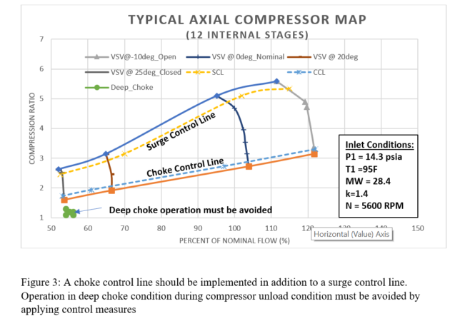
During start-up and under unloaded operation, too, choke can occur when the
anti-surge valve is opened too much or for too long, and no back-pressure is created by the process. If the anti-surge valve is oversized, high travel limitation (clamp) must be established in the controller to make sure the compressor operating point enters the stable operating envelope as soon as it starts and remains there during operation in unload condition. It is vital to
avoid compressor operation in a deep choke condition from the beginning of
startup (Figure 3).

Another choke condition takes place during loaded operation in combination
with excessive opening of the anti-surge valve due to manual operation or by valve low travel limitation (clamp) set by the operator. The operator sometimes applies low clamping during startup while the process is stabilizing to add extra cushion and prevent surge or fast opening of the antisurge valve by the control system.
In centrifugal compressors, low clamping wastes energy. But in axial compressors, it may also push the blower into the choke area (due to the narrow operating area between surge and choke). Therefore, clamping must be avoided or used with special care with axial compressors.
One further choke condition should be noted: In compressors operating in parallel, when one compressor trips, the natural response of a load sharing control system is to increase the performance of the running compressor to compensate for the loss. However, if process resistance remains unchanged, the running compressor will be pushed into the choke area.
To avoid such conditions, certain control measures should be implemented:
• Install an anti-choke valve immediately downstream of the anti-surge blowoff/recycle line and set up proper antichoke control, which must be independent from the anti-surge controller. Separate transmitters must be used as the distortion of a shared transmitter signal may have conflicting effects on the anti-surge and anti-choke controllers
• Make sure the process is always ready to provide enough back-pressure for
the compressor as soon as it is started. For example, place an initial set point of 10-15 psig at the FCCU regenerator. The slide valves should also be kept closed at the mechanical stop to help creating back-pressure. In the case of power recovery trains, the expander inlet and bypass valves can stay closed during startup of the train. If an anti-choke valve is present, start the compressor with that valve initially closed, then slowly ramp it open
• Perform a choke test in addition to a surge test to determine the choke line and establish a choke control line. Make sure the compressor can operate safely in the area close to the expected choke limit. A portable accelerometer can be used to determine if the axial blower is operating in a choke condition. In the author’s experience, radial vibration or axial displacement do not increase in a deep choke condition. An accelerometer placed in the casing
near the blower inlet has shown a clear acceleration peak when operating in a choke condition. At higher performance levels, choke can also be perceived by
a variation of the normal operating sound
• Graphically illustrate in the HMI the exact location of the choke line, surge line and control lines. As choke is not noticeable (unlike surge), it is
vital that it be graphically shown on a real-time compressor
map
• When operation near choke is detected, the control system should generate an alarm. In the absence of a choke valve, the operator may be able
to apply corrective measures, such as increasing the regenerator
pressure
• Properly size and test the anti-surge valve to make sure it does not allow for operation in choke when 100% open in an unloaded condition. The
selection criteria for the capacity of anti-surge valves may be different for axial compressors compared to centrifugal
• Have an advanced diagnostic tool that stores high resolution trends and events so catastrophic damage can be correctly attributed
• It is recommended that vendors develop and install an additional signal to the vibration system, such as an accelerometer from the compressor
case to generate an alarm and trip due to operation in choke condition for a certain period of time.
Leyden Lopez is Director of Leyden Turbomachinery Corporation of Houston, TX, providing commissioning and consulting services on turbomachinery controls. For more information, visit www.leydentcs.com