AERODERIVATIVE USERS SHARE MAINTENANCE TIPS
USER GROUP EXAMINES TURBINE RELIABILITY, LMS100 FLEET BUIL OUT, MAINTENANCE BEST PRACTICES, HRSG PERFORMANCE AND THE REAL COST OF CYCLIC OPERATION
Users of GE LM2500, LM5000, LM6000 and LMS100 aeroderivative gas turbines assembled in San Diego, CA in March at the Western Turbine Users, Inc. (WTUI) conference to find solutions to real world problems. Over a thousand members — second highest-ever attendance — gathered there.
These technical support personnel, who live, breathe and think every detail of the aeroderivative, are given the opportunity to ask the OEM tough questions regarding the operation and maintenance of its equipment. The goal of the conference is to serve the user.
Sharing ideas
“Our mission is to advance the reliability and operability of the GE line of aeroderivative gas turbines,” said Jon Kimble of Wellhead Services, President of WTUI. “The purpose of this gathering is to share ideas, display products and techniques, and act to help our membership meet their goals.”
After a short introduction, Don Haines of Wood Group GTS, chairman of the LMS100 track, introduced speakers from GE for three days of intensive briefing, discussion and Q & A on every aspect of turbine operation and maintenance. Haines prodded users for feedback and informed them about Technical Information Letters (TILs), relevant service advisories for plant equipment issued by GE.*
Phil Tinne, GE’s Technical Sales Support Manager for the LMS100, began the track with an overview of the turbine. It had accumulated 173,870 operating hours, with a high time unit in Argentina at 29,037 hours, which runs at base load most of the time. The total LMS100 starts worldwide are 24,313, with 28 units in commercial operation at the end of 2012. Most are simple cycle, but five LMS100s are running in combined cycle mode.
“Another 23 units are being installed or commissioned,” said Tinne. “Nineteen of these new units are at three sites in Southern California. They have already been running for about 1,000 hours collectively and will be in full commercial operation in the near future.”
In addition, the first two Dry Low Emission (DLE2) versions of the LMS100 are being installed in Russia. They will support the Winter Olympics but are being brought online this summer so they are ready for the games.
New additions to the LMS100 include: a top-mounted air filter with built-in crane; a high-temperature intercooler, which halves the size of the turbine’s dry cooler; the DLE2 combustor; and minor hot-day power adjustments for those with dry cooling.
GE specialists then delivered nuts and bolts maintenance-related guidance and tips. Topics included: nickel cadmium batteries versus lead acid technology; hydraulic starter oil analysis; and fan vibration. In addition, a series of TILs were reviewed or touched upon, covering a dizzying array of issues:
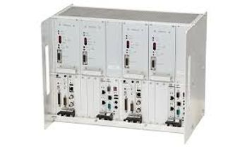
• Replacing the LMS100’s injection metering valve for demineralized water with an upgraded NOx-water valve • Updating the Det-Tronics Eagle Quantum Premier software, as well as how to troubleshoot a fault in the fire-protection system’s processor
• Addressing Compact Flash Module Corruption in Mark Vie Controllers
• Replacing the LMS100 Air Conditioning units
• Introducing tubing improvements to the Turbine Hydraulic System Auxiliary Skid
• Using an Inlet Guide Vane (IGV) Oring kit to replace the Servo Valve Filter Assembly and related components
• Adding an authentication selector switch for manual operation of the Mineral Lube Oil AC pump starter buckets.
Toward the end of the LMS100 track, William Trevino, Machinery Diagnostics Lead at GE Bently Nevada detailed the LMS100 vibration system. He discussed the layout of dozens of vibration sensors and probes stationed throughout the engine, how the Human Machine Interface (HMI) correlates to the sensors, the proper software configuration and the system’s alarm and trip logic. He added tips on how to troubleshoot the system.
Reliability data
Each year the WTUI conference board invites speakers from Strategic Power Systems (SPS) to provide a summary of aeroderivative reliability and performance. This is based on the SPS Operational Reliability Analysis Program (ORAP), which is taken from actual GE aeroderivative users.
For the LMS100, ORAP received information from units representing over 80% of the fleet. “Overall, the LM100 fleet has achieved a reliability level of 98.5%, with availability at 96.7% and starting reliability at 98.6%,” said Salvatore DellaVilla, Jr. CEO of SPS.
He relayed the top ten contributors to forced outages by incident. At the top of the list were engine controllers, computing and software issues. These were followed by combustion systems. Other causes of forced outage incidents included exhaust thermocouple temperature spread, grid instability, liquid fuel drain valves, inlet air filters, lightning, excitation AC voltage regulator and the lube oil check valve (Figure 1).
Of the incidents reported with regard to engine controllers, most were down to communication or controller failures, added DellaVilla. Others were due to false pressure indications from software controls (being addressed in the latest software updates), and a few because of failure to start, burned-out circuit boards, and bleedvalve- module malfunctions.
HRSG advice
Maintenance best practices for Heat Recovery Steam Generation (HRSG) were covered by Ned Congdon, a systems engineer from HRST, a Minnesota-based company that does inspection, analysis and repair of HRSGs, as well as coil replacement, tubebank cleaning and maintenance. He started with expansion joints, showing how the joints themselves could experience their own expansion problems, which can lead to cracking. If this is the case, his advice was to use bolting rather than welding.
He also provided a wealth of best-practice tips on liner insulation maintenance.
“Sandwich the liner between two washers so it can’t vibrate toward or away from the casing,” said Congdon. “If you use oversized holes, the liner can expand and contract without cracking.”
Additionally, liner panels should be relatively thick (10 gauge) and arranged like fish scales away from the direction of the gas flow so the exhaust flow cannot easily get underneath and cause damage.
Further tips: use ¾” - 1” diameter studs and maintain only 12” distance between them; if the casing is visibly vibrating, add external stiffeners; use ceramic fiber, not mineral wool, in HRSG inlet ducts, as the mineral wool binder burns out above 500°F and becomes weak; compress the insulation so that it fills the insulation space; complete inspections should be done yearly, but keep a closer eye on the inlet and firing duct liners as that is where problems are most often found (Figure 2).
“Check near the GT for loose panel cracking, exposed insulation, spinning washers and air scoops; and fix what you find without delay,” said Congdon. “Check near burners for creep, oxidation and flame impingement.”
He strongly advised users not to weld liner sheets together. This may be a quick fix but in his company’s experience, it leaves a bigger mess for the next inspection. However, he did recommend that some washers in high-velocity zones have full circumferential welds between the stud and outer washer, and a tack weld between the stud and the inner washer. The LM6000, he said, generates a lot of air flow within the HRSG.
Liner issues often arise in relatively small areas on walls near burner elements. In such cases, some relief can be obtained by plugging 50% of burner element fuel nozzles within a 2-foot distance from the wall.
Congdon ended with coverage of fouling by rust and ammonia salts. Fouling, he said, leads to a rise in turbine exhaust back pressure. As many turbines include a high back-pressure trip, it is unwise to ignore this symptom.
Also, for many turbine models, an 8” increase in back pressure reduces GT power output by about 1%. Takeaway: know what your back pressure should be, what it is, and what back pressure will trigger alarms or trips. If you have excess back pressure, take on-line, gas-side dP measurements and perform outage inspections with a borescope to determine where the fouling is located (Figure 3).
“While a gradual increase in back pressure usually means fouling, a rapid rise probably indicates liner failure,” said Congdon. “But don’t wait till the tube fins are totally packed with ammonia salts, as it takes far longer to clean.”
Common HRSG cleaning methods include CO2 blasting with dry ice, compressed air blasting and hydroblasting. HRST has its own Deep Cleaning method, which is said to reach five-to-seven rows into the HRSG. “It is difficult to get far into the HRSG bundle,” said Congdon. “HRST developed Deep Cleaning tools which can be combined with CO2 and air blasting techniques to clean fouled tubes deep in the bundle.”
The second day at WTUI ended with Dwight Agan, Project Manager for the Power Group of Intertek AIM (Sunnyvale, CA), revealing the true cost of cyclic operation in power plants. His company has completed such studies in over 400 plants.
The general concept is that there is substantial wear and tear related to cycling that needs to be understood and taken into account as a production cost. By unbundling and quantifying its various aspects, operators can become better informed about the best ways to operate their facilities in terms of long-term profitability and longevity.
“Modern power plant designs have tended to compromise physical robustness for higher efficiencies and lower installed costs,” said Agan. “Some units are better designed for cycling than others, while some are so bad or the service duty and ramp rates so severe that the HRSGs experience forced outages within a hundred on-off cycles. Other units can cycle on a daily basis without major problems despite thousands of onoff cycles.”
Every time a combined cycle plant is brought online, shutdown, or used for load following, the GT, steam turbine, HRSG, steam piping and auxiliary systems are subjected to expansion and contraction, which lead to thermal and mechanical fatigue damage, as well as corrosion fatigue, water chemistry transients, creep, erosion and vibration. These collectively eat into life expectancy.
Take the case of a large GT starting three times in one day. Exhaust gas temperature, power output and exhaust temperature ramp rates plotted by the hour can highlight the types of operation which exert the most damage on a facility.
The first start is a cold start, followed by a warm and then a hot start. In this example, the exhaust gas temperature spikes to 2,780°F in the cold start, which also has the highest ramp rate. This equates to the most amount of equipment degradation. The second (or warm) start temperature peaks at 1,955°F, while the third falls to 1,425°F.
“Such differences in ramp rates between the various cycles are of extreme importance when determining the stress levels and amounts of thermal fatigue damage accumulated by the GT and HRSG,” said Agan. “The slower you ramp, the less damage you accrue. Ideally, you should be doing mostly hot starts and ramping up slowly. You can do a lot of damage with fast ramping warm and cold starts.”
A similar situation occurs in the HRSG when the duct burner is activated or shut off, or when the gas turbine is dispatched in a load following mode. Agan said that temperature shifts occur among the individual HRSG tube circuits and that these result in additional thermal and mechanical fatigue cycles.
Since the components are densely packed and rigidly supported to optimize the amount of heat recovered from the exhaust, flexing of tube-to-header connections and transfer piping nozzles imposes stress on connections, which then leads to cracking and tube failures.
Part of the concern is that most cycling calculations take into account only the additional fuel costs. This is too shallow a view. The drop in efficiency due to variable load operations, for example, can impact the heat rate anywhere from 2% to 20%. Thus one must determine the overall heat rate effects for each type of cycling (Figure 4).
Accordingly, Intertek has developed a methodology to break down and monetize these impacts. Its top-down approach uses past operational histories, forced outages and overall costs, whereas its bottom-up method relies on calculations of operational stresses (temperature, pressure and chemistry) life expenditure of components, and an analysis of historical work order costs.
In Intertek’s experience, most plants pair a fast ramp with a cold start and tend to ramp slower with hot starts. If they desire longevity and much lower maintenance expenditures, they should be doing the opposite. Yet, the heavy integration of renewables onto the grid seems to demand a rapid ramp from a cold start.
Next year’s conference returns to Palm Springs, California. For more information: www.wtui.com.
* Haines also hosts a monthly LMS100 user group call, which takes place on the first Wednesday of every month. To find out more about the LMS 100 User Group and its regular calls, visit: http://groups.yahoo.com/group/lms100ug/
Newsletter
Power your knowledge with the latest in turbine technology, engineering advances, and energy solutions—subscribe to Turbomachinery International today.


