Avoiding speed instability in steam turbines

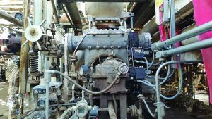
A mechanical actuator was changed to a REXA electraulic actuator in order to improve steam turbine reliability and performance[/caption]
By Dave Nelsen and Mike Murphy
Decades-old low-tech mechanical and hydro-mechanical governor equipment continues to operate with many turbines in refineries and process plants. This equipment can present maintenance and operational challenges. It can lead to reduced efficiency and reliability in the production process.
The job of the turbine speed governor is to provide accurate speed control, thus preventing process oscillations and unplanned shutdowns, and improving process throughput. To achieve this goal precisely and dependably, it is advisable to perform a governor valve actuation retrofit.
Advantages include stabilization of equipment speed with tighter rpm control, and avoiding nuisance process and equipment trips. This enables the turbine to operate at its maximum potential without interruption.
Compressor Controls Corporation (CCC) recently implemented a mechanical retrofit for a U.S. refinery experiencing large swings (100-200 rpm) in the speed control of a steam turbine (ST). Speed instability was caused by a subpar governor valve actuation system. The sticking actuator could not maintain the setpoint target and had recently caused a process trip of the main air blower.
Sticky actuators
Difficulties with speed control meant the ST had to be operated manually and at a higher target speed than desired. In addition, load sharing with a secondary air blower could not be implemented, and the operator had to use the blow-off valve to adjust the air flow. Additionally, the ST could not use the existing CCC automatic start-up sequence because of the sticking actuator.
The actuation system specified was a REXA Electraulic self-contained unit. It uses a position-controlled power module driven by a 4-20 ma signal to turn an internal oil gear pump that displaces hydraulic fluid from one side of cylinder piston to the other.
A rod extending from the cylinder is mechanically connected to the steam valve rack and able to position the rack from the closed to open position. The system has no need for an external oil supply source.
The actuation retrofit was executed during an unscheduled outage. As a result, the turbomachinery train could more accurately match its performance with the desired process set point. This also allowed use of the automatic startup sequencing and load sharing features of the CCC control system.
Controlling compressor efficiency starts with precision control of the ST driver in order to regulate the speed of the compressor. Actuator upgrades depend on turbine design. For turbines with shell-mounted control valves, the actuators may individually drive multiple control valves, or there may be a single power piston arrangement that drives a bar or rack allowing multiple steam valves that are mechanically coupled together to be opened sequentially.
For turbines with chest-mounted control valves, it may be a globe-style valve external to the turbine that is providing the control. In some configurations, a pilot valve assembly with a small stroke and a low thrust requirement may be used to port lube oil to the power piston. Typical ST control requirements include 0.1% repeatability, 100% duty cycle, <100 m/sec dead time, fail-safe capability, the ability to withstand high ambient temperatures and a fast stroking speed (less than 1-2 seconds for full stroke).
Steam turbine designs at this refinery used a system comprised of a hydraulic power unit (HPU) and servo or proportional valves for control. These hydraulic systems were proven to meet and exceed turbine control requirements when operating in design conditions. But after time, the system required extensive oil maintenance for proper operation.
Many traditional hydraulic systems are open-loop, using an HPU, a gravity fed reservoir, and a series of servo or proportional valves for control. These systems need a lot of oil and all use the same principal of operation. Hydraulic fluid is drawn from the reservoir by motors and pumps to facilitate movement of the actuator cylinder and is drained back to the reservoir when the cylinder moves to position. The oil is continually circulated at high frequency to accomplish the high resolution control performance required for the application.
Since the system is open to atmosphere at the reservoir, the oil is subject to breakdown. Exposure to the atmosphere adds moisture that causes degradation to the oil system due to moisture ingress, oxidation and corresponding acid build-up. The continuous circulation of hydraulic fluid adds heat to the oil, which accelerates breakdown of the hydraulic fluid. To combat the effects of oil breakdown, system owners are required to perform maintenance, use filtration systems, and replace hydraulic fluid, which degrades, causing sticking in servo and proportional valves.
Electraulic actuators are designed for continuous modulating service with an adjustable dead-band that is .05% of stroke. This provides repeatable, stiff and accurate control performance, and eliminates filtration and oil maintenance.
Authors: Dave Nelsen is Turbomachinery Controls Engineer at Compressor Controls Corp. (CCC), which offers consultation on advanced controls. For more information, visit www.cccglobal.net
Mike Murphy is Marketing Manager at REXA, which manufactures a complete line of industrial grade linear and rotary self-contained electro-hydraulic actuators and damper drives. For more information,
visit www.rexa.com