COMBUSTION TURBINE EXHAUST DUCTS
PROBLEM AREAS FOR TURBOMACINERY EXHAUST DUCTS MUST BE UNDERSTOOD AND SOLVED TO ACHIEVE OPTIMAL PERFORMANCE
BY SCOTT OLSON & KEVIN MORALES
Power plant gas turbine (GT) exhaust ducts are exposed to challenging conditions that require diligent inspection and maintenance to keep the ducts reliable. The consequences of not maintaining this duct section include: Expansion joint failures from fabric overheat; internal liner plate and insulation liberation, which results in fouling of Heat Recovery Steam Generator (HRSG) tubes and Selective Catalytic Reduction (SCR) catalysts, creating high turbine backpressure; and casing hot spots, greater than expected expansion and casing cracks.
Two common problems often encountered during inspection and troubleshooting are cold casing internal liner stud failures, and hot-to-cold casing transition cracks and hot spots. Understanding both conditions can be of material help to plant operators.
Cold casing
Let us look first at cold casing internal liner and insulation system stud failures. The typical GT exhaust duct has internal liner plates protecting the internal insulation and one or two expansion joints that connect the duct to the turbine and the downstream ducts for the HRSG or stack. The external cold casing is usually carbon steel. The internal liners plates are typically either SS304 or SS409 materials secured with SS304 studs. The internal insulation thickness is around six inches, which allows the external casing to operate at or below 140°F if all is working properly.
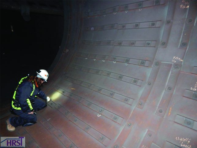
With each turbine start, this duct section must withstand a temperature change from ambient to 900+°F in seconds. As the temperature change occurs, the exhaust velocity increases to greater than 100 feet/second, with swirling turbulence. F-class turbines, such as the GE 7F and 9F, often have a round diffuser duct between the GT and the downstream HRSG or stack (Figure 1). As fired hours and starts accumulate, so do the chances of finding broken studs in this section.

Figure 1: F-class turbines often have a round diffuser duct between the gas turbine and the downstream HRSG or stack. As fired hours and starts accumulate, so do the chances of finding broken studs in this section
The studs anchor the internal liner plates and if adjacent studs fail, the internal liner plates can vibrate and liberate. This results in an immediate casing hot spot. If there is an HRSG with an SCR downstream, there is also a jump in turbine backpressure from insulation sent downstream in the direction of gas flow. The insulation commonly accumulates on boiler tubes or CO/SCR catalyst systems.
Outage inspection in the diffuser duct section is usually a matter of, “how many broken studs will be in this one?” The inspection often triggers the need for scaffold installation and broken stud repair, especially if there are multiple failed studs supporting a single liner sheet, due to the risk of liner sheet liberation. Repairing broken studs can reveal these problems:
- Holes in the liner sheet that the stud passes through are not aligned and are too small to accommodate plate expansion and contraction. This creates interference between the stud and liner panel
- Large liner sheets size and expansion over the length of the sheet causes stud and hole interference
- Poor weld fusion of the dissimilar metal weld between the stud and the scallop bar during fabrication
- Broken scallop bars that weaken the stud and liner sheet support
- Liner plate cracks propagating from the liner sheet holes.
Experience in dealing with this issue points to two solutions: Broken stud repair options to deal with repairs to keep the existing system functional; and a redesigned liner system to replace the existing design when repair maintenance and reliability risks become excessive.
Stud repair: Fixing a broken stud requires patience and planning, and often some scaffolding. The stud-to-scallop plate weld failure area must be properly exposed to check the condition of the scallop plate, repair it if cracked and weld a new stud to the existing scallop. While performing this repair, liner plate hole alignment should be checked and improved, and holes enlarged if necessary. This process is fine for five-to-ten broken studs. But if that number keeps climbing each year, replacing the entire stud support and liner system should be considered.
Duct stud and liner upgrade: There are many factors that make for a reliable liner design. Liner sheet size controls overall expansion and contraction of the sheets during all operating conditions. Properly sized stud holes are another key factor. Ensuring that each liner stud is centered within the liner sheet hole during installation is paramount. A robust stud design that is carefully attached to the outer shell and carefully located is critical. The design of the studs and liner plate system should control the direction for which the liner panels expand and contract during startups and shutdowns.
A retrofit was done of a 16’ diameter x 31’ long diffuser duct liner system after 12 years of cycling service. The duct is located downstream of a GE frame 7FA turbine. Prior to the retrofit, the plant had been making repairs to the original liner during every planned outage. Maintenance costs were increasing from one outage to the next. Then the plant suffered a liner sheet failure and insulation fouled an HRSG CO catalyst, resulting in a 4-inch water column (WC) increase in backpressure. This event resulted in an outage so a repair could be made and the CO catalyst cleaned.
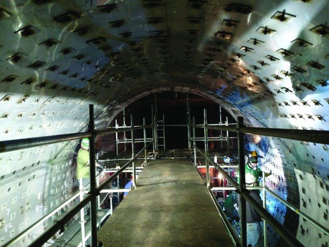
Shortly after, the new system was ordered. Demolition of the old system revealed the full extent of the stud-weld cracking and scallop-plate cracking problems. Installing the new system required carefully designed liner plates, studs and stud spacing in the slightly cone-shaped duct (Figure 2).

Figure 2: New liner system with carefully spaced studs
Installation methodology was also important since scaffolding installation and removal had to be coordinated between the demolition phase of the top half and bottom half. These improvements reduce the risk of liner failures and lower annual maintenance costs.
Hot-to-cold casing
The transition from the gas turbine exhaust outlet to ducting downstream can be a “trouble zone.” This area is typically a transition from a hot casing to a cold casing in a relatively short span, usually at an expansion joint.
Temperature differentials and metal expansion in this zone often lead to casing stress and cracking. Casing cracks then allow hot gas leakage, which causes more casing heat problems and additional issues. These include gas leaks, personnel burn hazards, insulation voids, and overheated fabric expansion joint material. Sometimes attempts are made to “beef up” the arrangement with the addition of stiff structural members or layers of extra weld to repair cracks. This kind of “more is better” fix generally offers little help. In fact, they can worsen the situation if not applied correctly. Ironically, many expansion joints simply are not designed to adequately facilitate the hot-to-cold transition.
Another project involved an LM2500 gas turbine. Its exhaust transition piece to the HRSG gas inlet ducting had cracks. The transition duct and expansion joint had been replaced more than once. The original design included two back-to-back flanges with heavy gussets transitioning from a small 5ft x 7ft inlet to a larger 6.5ft x 9ft outlet in the span of only nine inches. The outlet was bolted to an expansion joint transitioning from a hot casing to a cold casing. With 850+°F exhaust gas temperatures, the carbon steel transition piece was overstressed. It suffered from chronic cracking. The expansion joint, designed only to accommodate axial movement, pulled double duty as it had to also endure extreme thermal expansion at the hot gas inlet.

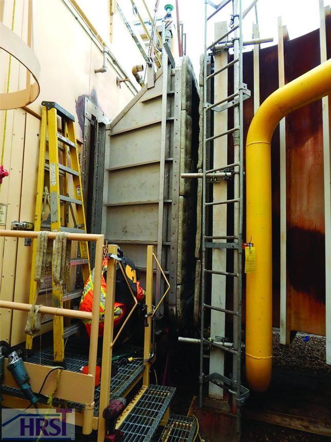
Figure 3: Hot-to-cold expansion joints often cause hot spot problems. Seen here is a new hot-to-cold transition duct
The solution was to develop a longer transition duct allowing for a more gradual hot-to-cold casing transition (Figure 5). The duct was internally insulated from zero inches of thickness at the gas inlet to full thickness at the gas outlet. A heavier outer casing with properly designed reinforced corners made the duct capable of managing the points where stress typically is concentrated. As there was zero insulation at the gas inlet, high temperatures to the outer casing had to be addressed. Stainless steel was used for the outer casing in place of the typical carbon steel. The result was a duct capable of managing transient temperatures and thermal expansion. Outer lagging was attached to low rise stiffeners to help dissipate the heat from the hot casing. The transition duct redesign also improved the expansion joint arrangement.
When GT exhaust expansion joints fail, there is a high probability it can be attributed to the outside fabric being exposed to hot gas over a prolonged period. This hot gas exposure may well come from a compressed or bunched-up insulation pillow from the many cold-to-hot-to-cold cycles. Other common issues include components that are overly stressed from excessive or transient temperatures, and components that bind up because they are not able to move freely due to thermal expansion.
Given that that the new transition duct was designed with a cold casing outlet, the replacement expansion joint could be approached as a cold-to-cold design vs. the existing hot-to-cold design. This eliminated the “double duty” considerations of the previous joint. A flexible pillow under the outer fabric was also used. The pillow could expand and compress, yet still hold its shape during hot-to-cold cycling. This avoids the creation of insulation voids that can lead to outer fabric hot spots. Thermal breaks between the inner and outer hardware further reduce conductivity of heat to the outer casing. All components work together to reduce the operating temperature of the outer expansion joint fabric, prolonging the expansion joint longevity.
Authors: Scott Olson is Project Manager at HRST, a provider of power plant boiler technical services for HRSGs and waste heat boilers. Kevin Morales is Project Manager at HRST. For more information, visit www.HRSTinc.com