GAS BEARINGS
LUBRICATING TURBOMACHINERY WITH GAS BEARINGS
By Drew Devitt, New Way Air Bearings

Almost all fluid film lubrication applications in turbomachinery use hydrodynamic, (in the case of oil) or aerodynamic (in the case of gas) bearing technology. This type of lubrication uses the relative shear between the bearing faces and the rotor to drag lubrication into the natural wedge-shaped gap that forms between them.
The other type of fluid film bearing is a hydrostatic or aerostatic bearing. This bearing creates lift even at zero RPM as it employs an external pressure source and some type of restriction or compensation to create a pressurized film of gas to carry the load.
Dry gas seals
DGS are face seals that use machine work or etching to create grooves in the faces. These grooves pump gas into the gap from the high-pressure side to increase pressure.
DGS are also balanced. Hydrodynamic pumping grooves in the face of the seal create enough extra pressure in the gap to keep faces from touching. DGS have virtually replaced all oil seals in new compressor builds.
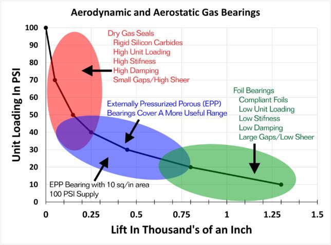
Shear losses in fluid film lubrication are a cubed function of the gap. Very small gaps can generate a lot of shear heat, even in gases. Therefore, DGS seal faces are often made from rigid and thermally stable silicon carbide to keep them flat. If the gas gap is only a few microns, the relative flatness needs to remain less than the gas gap. This is higher unit loading than can be achieved with hydrodynamic oil bearings.
Foil bearings
Foil bearings are another type of gas bearing that employ aerodynamic lubrication. The first production foil gas bearings were developed for the DC-10 in 1969. Today, virtually every medium to large aircraft uses them.
Foil gas bearings have shown long-term reliability. Many have demonstrated operation on other working fluids such as hydrogen, refrigerants, liquid oxygen or supercritical CO2. The ability to operate at cryogenic or high temperatures is another advantage. Gases also take heat better than oil, and do not change their viscosity much. Foil bearings are commonly used in blowers for water treatment processes, sub megawatt gas turbines and turbo chargers.
Bump and overleaf are the most common types of foil bearings. The bump foil bearing (BFB) consists of a thin flat piece of spring steel stamped to have bumps. A top foil is inserted into the ID and is supported by the bumps. Instead of a continuous top foil, the overleaf employs separate, stiffer overlapping leaves with longer bending moments for low stiffness over a larger range.
Aerostatic lubrication
Aerostatic or externally pressurized gas bearings can provide lift even at zero RPM. Although they do not have fine pumping grooves like dynamic bearings, they require some type of restriction for metering the gas into the gap. Air pressure is introduced directly between the bearing surfaces though holes, orifices, grooves, steps or porous compensation techniques.
Compensation enables bearing faces to run close together without touching. The closer they become, the higher the gas pressure repelling the faces. Under a gas bearing, the average pressure in the gap equals the load on the bearing divided by the face area (unit loading). If the source gas pressure is 100 psi, the seal face has 10sq.in. of area and there is 600 lbs. of load, there will be 60 psi in the bearing gap. If the load increases, the gap reduces as there is a restrictor before the gap.
Orifice compensation is the most widely used. Orifices are placed on the bearing face and are often combined with grooves to distribute the pressurized air across the face. If the face becomes scratched, the air that escapes may be more than the orifice can supply, leading to contact or crash. They can also be plagued by contamination.
Porous compensation
The ideal gas bearing design would supply pressure equally across the face of the bearing and automatically restrict and damp the flow of air. This can be achieved by diffusing air through a porous bearing or seal face. Graphite and carbons may be used for this purpose. A damping effect (from passageways the gas flows through) makes it difficult for air volume in the gap to change quickly. This results in a stable gas film that cannot be plugged by particulate. In case of contact, graphite is an excellent plain bearing material.
Porous compensation also works well for small gaps and small flows. There is zero lift and zero flow, yet zero load and friction between the faces. The load is taken by the air pressure acting like a hydraulic cylinder. It is not recommended to run a bearing in this mode, but it is another example of why porous compensation has better crash resistance and is more robust then orifice compensation.