How to install hydraulic hubs on turbomachinery
PROPER INSTALLATION IS CRITICAL TO TRANSMITTING TORQUE CONSISTENTLY AND RELIABLY
By Pat McCormack

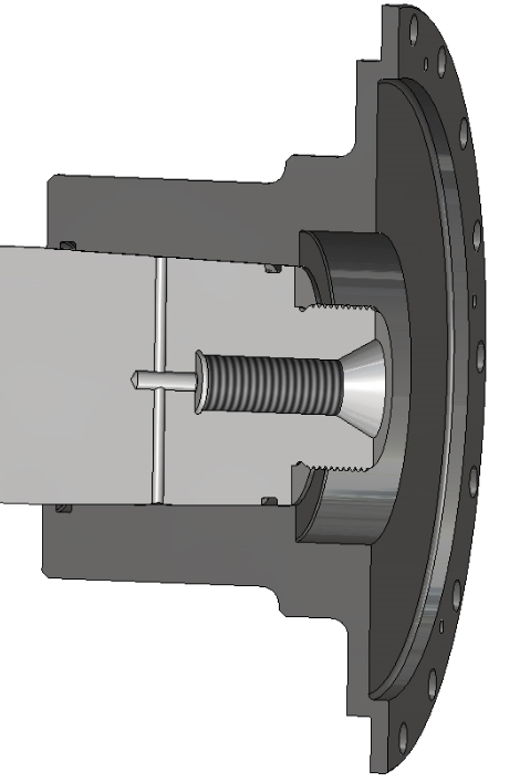
Caption: Hub with shaft end hydraulics.
The number of methods used to hydraulically mount tapered bore hubs onto tapered shafts is as numerous as the equipment manufacturers in the industry. Each Original Equipment Manufacturer (OEM) has its own design philosophy regarding the placement of O-rings, type of hydraulic fittings, and even the installation equipment to be used.
This article should not override methods defined by the OEM. It is intended to provide guidelines to help achieve the precise fit required between the shaft and hub and prevent equipment damage if proper procedures are not followed.
A common area of damage associated with hydraulic hub installation is scoring of the shaft or hub on the leading or trailing edges of the mating components.
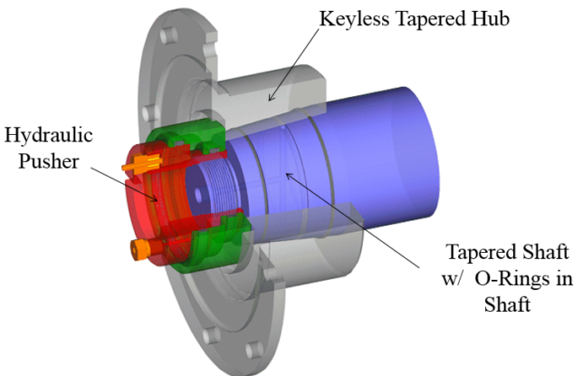
Configurations can vary due to the location of O-rings on the hub and shaft and the means used to introduce dilation pressure, which is used to expand the hub. A typical O-ring arrangement can be one O-ring groove on the shaft and the second on the hub.
Alternatively, both O-rings can be located in the hub, and occasionally, no O-rings are used. The dilation pressure can be introduced through the shaft end or through a radial passage through the hub.
Before beginning the installation process, be sure to clean the parts. The success of hydraulic mounting coupling hubs is dependent on the condition of contact surfaces. The hub bore and the shaft end must be clean and free from burrs.
The smallest particle trapped between the shaft and the hub bore can distort the hub enough to make the fit up unsuitable for use. Any nicks, scratches, and edges on mating surfaces must be polished smooth.
Checking for proper contact is the next step. According to API Standard 671 4th Edition:
“Para 8.6.2.6, Tapered bores shall be checked by using the plug gage from a matched plug and ring gage set provided by the purchaser. A light coat of bluing shall be used for the check. Tapered bores for keyless, hydraulically fitted hubs shall have at least an 85% blued fit (surface contact) to the taper gage.”
If less than the required 85% contact is found, and it can be attributed directly to nicks and scratches in the hub bore or shaft, this damage may be lightly stoned or polished to remove the high spots and then checked again with the ring and plug gage set.
If minimum contact of 85% is still not achieved, the shaft and hub should be independently lapped using a ring and plug lapping tool set to achieve the 85% minimum contact. Lapping the shaft with the hub is not recommended due to the possibility of forming a “step” on each mating surface at the point of initial engagement.
Once the tapers match with an 85% or better contact, set the Zero Start Position. Without any O-rings or back up rings installed on the shaft or hub, put the hub on the shaft with only hand pressure, pushing the hub onto the shaft.
The point where the hub stops advancing up the shaft is considered full engagement and is referred to as the Zero Start Position. This location is the initial position for starting the hub installation.
Once the hub is in the Zero Start Position, it is critical to take a measurement and record the distance the hub is from the shaft end. Using a depth micrometer, measure from the hub face to the shaft end. This value needs to be recorded for final use once the hub is fully installed. It is good practice to mark the hub and shaft location where the measurement was taken, so the same spot is used to measure once the hub is installed.
The Zero Start Position is important because the hub must be advanced up the shaft exactly the amount specified by the OEM, which is usually stated on the coupling drawing as the “pull-up” distance. This pull-up is the predetermined axial movement of the hub relative to the shaft which is made possible by dilation of the hub.
There are two popular methods for establishing pull-up distance:
• Dial indicator method: Locate a stable and flat stationary surface in relative proximity to the hub end on which to mount a magnetic base dial indicator. Set up the indicator to measure axial movement of the hub. This provides a direct and accurate reading of the desired pull-up distance.
• Stop ring method: In this method, a gap corresponding to the pull-up is established between the end of the hub and a stop ring. The stop ring is usually a split-ring mounted on the shaft. It is common to use feeler gages or gage blocks to accurately set the distance between the stop ring and the hub, which establishes the pull-up distance. The stop ring should never be relied upon to act as a positive stop as the mounting tool forces will exceed the resistive force of the ring. Therefore, the stop ring should only be looked upon and used as a gauging fixture.
It is recommended that both methods are used to set the pull-up.
After the Zero Start Position has been determined and some method of measuring the pull-up is established, the hub can be removed. The last step in preparing the hub for installation is installing the proper O-rings and back-up rings.
The back-up ring is located on the anti-pressure side of the O-ring. It is imperative that the O-rings and back-up rings be kept clean and lubricated before installation. For lubrication purposes use the same hydraulic fluid that will be used to dilate the hub. It is also recommended that a light coat of the same hydraulic fluid is used to lubricate the hub and shaft interface areas.

Caption: The use of a hydraulic pusher is preferred to a lead hammer
Everything up to this point is in preparation for the installation. Skipping any of these steps will inevitably cause problems.
With O-rings and back-up rings installed, replace the hub on the shaft. When advancing the hub up the shaft ensure the O-rings and back-up rings are properly seated and not pinched or damaged.
More than likely, O-ring interference will prevent the hub from reaching its Zero Start Position. One accepted method of moving the hub up the taper is to use a lead hammer. Several blows of the hammer will seat the rings and allow the hub to move to the Zero Start Position. A more accurate way it to use the pusher tool to advance the hub to the Zero Start Position.
The pusher tool is designed to match the shaft end threads as it is required to be threaded onto the shaft at this location. The pusher tool is a hydraulic cylinder that will stroke enough to accommodate pushing the hub up the shaft the full pull-up distance. Once it is threaded onto the shaft end, it can be used to apply pressure to the hub, re-establishing the Zero Start Position.
An installation kit comprised of two hydraulic pumps is required. The two hydraulic pumps are manually operated, providing independent sources of both high pressure 35,000 PSI (241,320kPa) and low pressure 10,000 PSI (68,950kPa).
The low-pressure pump connects to the pusher tool and the high-pressure pump connects to the dilatation port (either in the shaft end or through a radial passage through the hub). Note that equipment damage and personal injury can result from mixing up the connections.
Before beginning the actual installation of the hub on to the shaft, recheck the Zero Start Position one last time. To begin installation, use the high-pressure pump and slowly increase pressure to about 12,000 PSI (82,740kPa) to begin dilating the hub. To prevent the hub from moving down the shaft as the dilation pressure builds up, use the low-pressure pump to develop sufficient force in the pusher tool to maintain the hub at its Zero Starting Position.
Some oil may bleed out between the hub and shaft joint. The degree of bleeding will vary from installation to installation which is a function of equipment arrangement and part tolerances. It is important that the hub be maintained at its Zero Starting Position as the initial dilation pressure is developed. Continue applying pressure using both pumps until conditions are stable before advancing the hub up the shaft. Stabilized hydraulic pressure should be in the range of 12,000 to 15,000 PSI (82,740 to 103,420kPa).
Using only the low-pressure pump, slowly advance the hub on the shaft continually monitoring hub movement with the dial indicator. As the hub advances, the dilation pressure (high-pressure pump) may rise without activating the pump. This dilation pressure may reach a level of 27,500 PSI (189,600kPa), but should not exceed 28,000 PSI (193,050kPa).
If it does, bleed off some of the pressure using the pressure release valve of the high-pressure pump until the pressure drops to 25,000 PSI (172,370kPa) before proceeding with further advancement. Caution: Always consult the OEM for the maximum dilation pressure as it is dependent on the hub material and the design being used. Continue to advance the hub to the pull-up position, always observing the high-pressure and low-pressure limits.
Should the low-pressure pump, connected to the pusher tool, reach its max limit 10,000 PSI (68,950kPa), stop the installation and remove the hub to inspect it and the shaft for damage to determine possible causes of the hang-up.
When the specified pull-up has been reached, the dilation pressure from the high-pressure pump can be slowly relieved to zero. Then disconnect the hose from the hub or shaft. It is important not to relieve the pressure on the low-pressure pump connected to the pusher tool.
After waiting a minimum period of one hour to allow the hydraulic oil to drain from the hub to shaft interface, release pressure at the low-pressure pump very slowly. At the same time, keep a close eye on the dial indicator to see if there is any movement of the hub.
If noted, stop releasing the pressure and hold for approximately 15 minutes then release pressure again. When all movement has ceased, the pusher may be disconnected from the shaft end.
Once the pusher tool and all hoses and fittings are removed, a final measure of the pull-up distance should be done using the same depth micrometer in the same location as the initial measure taken for the Zero Start Position.
This measurement should be the pull-up dimension from the drawing used in the installation process. If less than specified, repeat the installation procedure. If pull-up is greater than specified, it would be best to remove the hub and restart the entire process.
Author:
Pat McCormack is Director of Business Development at Riverhawk Company. For more information visit, www.riverhawk.com, call 315/768-4855 ext. 144 or email
pat.mccormack@riverhawk.com