LABYRINTH SEAL ALTERNATIVE
IMPROVE ROTATING EQUIPMENT PERFORMANCE WITH DYNAMIC, NON-CONTACTING SEALS THAT ARE PRESSURE-BALANCED
BY HARRY MILLER

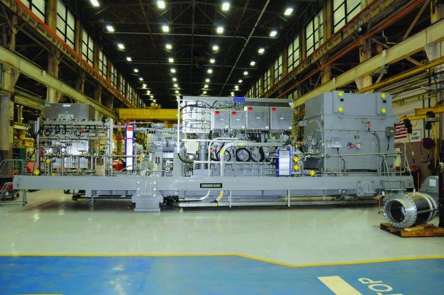
Figure 1: One of four Dresser-Rand Datum compression trains containing Dynamic Pressure-Balanced (HALO) seals destined for offshore installation in the U.S. Gulf of Mexico prior to shipment
Seals play an integral role in turbomachinery applications. In addition to minimizing leakage and recirculation power loss, effectively sealing the fluid flow path between rotating and stationary components is critical to reducing emissions, lowering fuel consumption, and maximizing equipment uptime.
Several types of seals can be used to perform this function, including labyrinth seals, pressure-activated leaf seals, finger seals and brush seals. Labyrinth seals come in a variety of forms — stationary, rotating, stepped — and are found in a wide range of rotating equipment applications throughout the oil and gas sector.
Most labyrinth seals feature simple toothed designs comprised of grooves that press tightly inside an axle so that fluid contained within the housing travels through a long and difficult path to escape. The tortuous flow path produced by the teeth also helps protect against the ingress of contaminants. For labyrinth seals on rotating shafts, a small clearance must exist between the tips of the teeth and the running surface of grooves for sealing to be effective.
Thus, labyrinth seals are typically made from a soft, abradable material (i.e., aluminum, bronze, Babbitt), which mechanically deforms when contacted by the rotor. This prevents damage to the harder base metal. Over time, however, continuous rubbing of the softer alloy creates additional clearance between the stationary labyrinth and the rotor, thereby increasing leakage by allowing fluid to recirculate around the flow path. In turn, energy consumption is increased and efficiency is reduced because more power must be applied to the rotor to maintain design flow rates and discharge pressure. Eventually, the compressor must be shut down for maintenance to replace the worn seals.
Pressure–Balanced Non-contacting, self-adjusting, dynamic pressure-balanced (DPB) seals have been designed to overcome many of the issues experienced by conventional labyrinth seals. They have proved to be effective in controlling leakage, reducing power consumption, and improving the reliability of rotating equipment.
Originally developed for use in the military aircraft and aerospace industries, noncontacting DPBs are compliant, self-adjusting, low-leakage seals that have been adapted for use in oil and gas turbomachinery applications (Figure 1). DPBs take advantage of the variation in hydrostatic pressures with seal tooth clearance to develop a force-balanced operational clearance as small as a few thousandth of an inch.
The acceleration of fluid between the seal and the rotor creates a low-pressure region that draws the seal toward the rotor. As the seal approaches the rotor surface, the velocity of the fluid decreases, resulting in a pressure rise that increases the outward force on the seal.
Seal dimensions are tuned to create the desired operational clearance. This is achieved when the outward force is balanced with the inward force from the upstream and downstream pressures acting on the backside of the seal. The clearance remains consistent throughout operation, resulting in less wear and leakage, and more reliable performance.
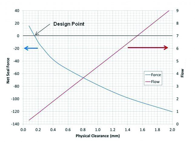
DPBs feature pads that are attached to fixed ring with a flexible spring. These shoes follow the rotor in real-time, maintaining the clearance set point via aerodynamic pressure balance. The seal can be set for any clear gap desired, and can accommodate both rotor offset and run-out variation during operation (Figure 2).

Figure 2: Shoe clearance vs. seal shoe force and shoe clearance vs. leakage flow. These typical analytical curves illustrate how net radial force increases as the seal pad approaches the rotor surface.
Comparison test
A test for a major oil and gas operator measured the performance of dynamic pressure-balanced seals vs. traditional labyrinth seals in a multi-stage centrifugal compressor designed for gas lift service offshore in the U.S. Gulf of Mexico.
The compressor is driven by a constant speed motor through a variable speed gearbox and uses seven impellers in a back-to-back configuration, driven through the high-pressure section. It employs a modular design with readily removable internals in a single cartridge assembly from the non-drive end.
The maximum working pressure (MWP) of the casing is 5,250 psi (362 bar). Each impeller is 10.49 inches (266.4 mm) in diameter and rotor maximum continuous operating speed (MCOS) is 13,881 rpm. The compressor was purchased with a standard aluminum tooth labyrinth design. The user requested that DPBs be installed and tested in parallel with labyrinth seals. In using the DPB seals, the client sought to maintain compressor efficiency and design flow leakages for longer run times between service intervals than conventional labyrinth seals, to raise the aerodynamic efficiency of the compressor and increase tolerance for rotor excursions.
To compare mechanical and aerodynamic performance, the DPB seals were designed to physically fit into the same operating envelope as the traditional aluminum tooth labyrinth seals. Static considerations, such as mounted component growth (from the interference fits of the impellers and interstage spacers), rotor sag (gravitational effects on the rotor), rotor bearing drop, and concentricity at each seal location were included in the DPB (non-activated) seal clearance to ensure that the rotor (non-rotating) did not come into contact with the DPB seals.
Baseline aero performance
An ASME PTC-10 Type II performance test was done to establish a baseline aero performance. This was compared to predicted performance with labyrinth seals, and an API mechanical run test was done. In addition, an ASME PTC-10 Type I performance test with Operational Modal Analysis (OMA) was carried out to determine rotor dynamic stability with labyrinth seals. This made it possible to evaluate the mechanical and aero performance of labyrinth seals.
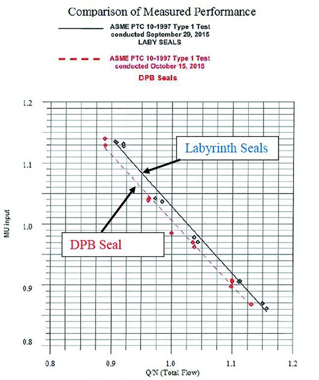
The same steps were then done for the rebuild compressor with dynamic pressure-balanced seals The results showed similar rotor behavior. The location of the first natural frequency, the amplification factor of the first natural frequency and the overall rotor vibrations at full speed were similar, which was consistent with predicted performance. OMA stabilization diagrams, modal distributions, and spectral data, showed no indications of significant changes in rotor dynamic stability between the DPB seals and labyrinth seals. Both systems are stable. The results of the ASME PTC-10 Type 1 aero performance test, however, indicated that 2.8% less power was needed across the entire range of inlet flow rates and pressure ratios for the DPB sealed compressor compared to the labyrinth sealed machine (Figure 3).

Figure 3: Full load, full pressure test results, work input (mu input) vs.
flow divided by speed. The solid line represents work input (mu input)
to achieve the desired head rise and delivered mass flow with the
labyrinth seals and the dotted line represents the same for the DPB
seals. The actual test data is shown with the open diamond shapes
while the lines represent a curve fit to the data points. The fact that
the two lines are nearly parallel indicates that the variability (i.e.,
uncertainty) between these two tests is low.
The performance test conducted on the centrifugal compressor demonstrated both the aerodynamic and mechanical-rotor dynamic integrity of the dynamic pressure-balanced seals for oil and gas turbomachinery applications. Most notably, the compressor with installed DPB seals required less power to achieve the same head level across the entire range of inlet flows and pressure ratios when compared to the same testing with conventional labyrinth seals.
After all the testing, the compressor was disassembled. Inspection of the hardware indicated no rubbing between the dynamic pressure-balanced seals and the rotor. This demonstrated that DPBs can maintain compressor efficiency and design flow leakages for longer run times between service intervals than conventional labyrinth seals. To that end, the client chose to ship the compressor to its location in the Gulf of Mexico with the HALO dynamic pressure- balanced seals installed.
Reference: “Meeting Motor Driven Compressor Base Package Design Requirements for Service on Floating Production Storage and Offloading Vessels,” Turbomachinery and Pump Symposium, 2015, by Harry Miller and Edward Abraham.
Author: Harry Miller is the Director of Emerging Technology at the Dresser-Rand business, part of Siemens Power and Gas Division. The Dresser-Rand business now offers the HALO seal – a non-contacting, self-adjusting, low-leakage dynamic seal for turbomachinery applications originally developed by Advanced Technologies Group. For more information, visit www.siemens.com