Performance modeling in diagnostics
MODELS ARE ACCURATE ENOUGH TO STUDY CHANGES IN GAS TURBINE PERFORMANCE THAT DRIVE MAINTENANCE NEEDS
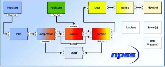
Figure 1: Typical Air Breathing Engine Block Diagram

One important aspect of condition-based maintenance is the current condition of the machine. Machine condition can be determined from physical inspections, but only at long intervals as these inspections lead to lost revenue while the gas turbine is not operating. Machine condition data also comes from monitoring of measured parameters during gas turbine operation.
This typically includes a sparse number of gas turbine cycle pressure and temperature measurements, rotor vibration measurements, and bearing lubricant conditions. While this information is valuable, it is often not enough to fully understand the health of individual components within the gas turbine system.
For example, knowing the compressor discharge conditions and the shaft power of the unit can allow for an estimation of compressor efficiency, but it does not provide more detail regarding the most likely stages of the multi-stage compression system that may be suffering reduced efficiency.
Ideally, a significant increase in the number of sensors could provide the fidelity of information required for more accurate diagnostics. However, this sensor density is reserved for much more expensive research and development units, not for production units.
As an alternative, it is possible to use a high-fidelity engine performance model to help the engineer see inside of the machine. Generally speaking, the engine performance models are owned and exercised by the same engineering teams that design and manufacture the gas turbine units.
These gas turbine performance models are used to perform preliminary design of new turbine concepts. During detail design, these same models are increased in fidelity to provide a system-level prediction of the total gas turbine performance while more specialized engineers make changes to individual component performance such as compressor or turbine stages.
Figure 2: “Measured” Compressor and Turbine Discharge Temperatures and Generator Power

System performance model
Every slight change in component performance is incorporated into the system performance model allowing the team to monitor their progress towards the design goal. When the engine is finally manufactured, the same performance model can be used to study engine performance data measured on the test stand.
The relatively sparse amount of data can be fed back into the model so that the system engineers can determine the most likely performance of each individual component. This last step — test data reduction — has potential benefit to the gas turbine owners. However, owners do not currently have the high-detail gas turbine performance models needed for data matching. To fill this void, some gas turbine operating companies are considering tools such as Numerical Propulsion System Simulation (NPSS) to develop their own gas turbine performance models.
NPSS is an engineering design and simulation environment that enables development, collaboration and integration of system models. Primary application areas include aerospace systems (i.e., engine performance models for aircraft propulsion), thermodynamic system analysis, such as Rankine and Brayton cycles, various rocket propulsion cycles, and industry standardization for model sharing and integration.
However, since it is fundamentally a flow-network solver, it has also been applied to a variety of other fluid and thermal subjects such as multi-phase heat transfer systems, refrigeration cycles, variations of common power cycles (i.e., Brayton), and overall vehicle emission analyses (Figure 1).
In a typical air-breathing engine block diagram the cycle is represented by the various thermodynamic processes, such as compression, combustion and turbine power extraction. When developing a model in the NPSS environment, the engineer specifies the type and order of the necessary components, referred to as “elements,” and provides the technical data that describe their individual performance. NPSS comes with a library of thermodynamic property databases and standard elements for use in engine cycle models.
Using such a tool, the operating company can develop a model of their particular gas turbine units using information they know from machine performance data and visual and physical inspection. They can tune their models to match the design-point performance of the machine and then incorporate as much or as little model fidelity as they deem appropriate for their own condition-based maintenance philosophy. Once the engine performance modeling is complete, the NPSS solver parameters can be modified to perform the data reduction role.
An example of such a solution is provided in which the “measured” compressor and turbine efficiencies are degrading with time. This example data is generated by using engine simulation to produce measurement data for specified combinations of compressor and turbine efficiency. The output is then used as simulated “measured” data for the data reduction solution using NPSS (Figure 2).
The measured parameters that are varying with time include compressor and turbine discharge temperatures and generator power. These measured parameters are similar to the parameters currently available to the gas turbine operator.
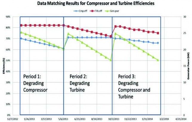
Figure 3: Data Matching Results for Compressor and Turbine Efficiencies

Feeding these measured parameters back into the engine performance model and adjusting the solution settings for the datamatching role, the simulation results indicate the change in compressor and turbine efficiencies necessary to match the combinations of compressor and turbine discharge temperatures for the associated generator power (Figure 3).
During Period 1, the solver correctly identifies that only the compressor efficiency is degrading. This is a common scenario and typically resolved with maintenance practices such as on-line or offline compressor washing. Depending on the number of relevant measurements available, more internal performance characteristics can be evaluated, such as performance of a section of the compressor.
During Period 2, only the turbine efficiency is degrading. This is a less likely scenario but could occur due to erosion or rub events. In Period 3, the data matching solver is able to distinguish the fact that both compressor and turbine efficiencies are degrading, resulting in the combined effect of loss of power in the generator. The solver is able to solve for multiple pairs of independent and dependent variables, which in this case include compressor and turbine discharge temperatures and compressor and turbine efficiencies.
Using this approach of data reduction, power generation operators can have access to higher fidelity information for use in their decision-making processes. Most of the information they need to generate these types of models can be determined from already provided machine performance data.
While such models may not be accurate enough to predict machine performance within guarantee levels, they can be accurate enough to study changes in machine performance that will drive maintenance needs. This will enable the gas turbine operator to have a more complete knowledge of their gas turbines current conditions.
Written by: David Ransom, P.E., & Jacob Delimont, Ph. D.

Jacob Delimont, Ph.D., is a Research Engineer in the Propulsion & Energy Machinery Section within the Fluids & Machinery Engineering Department at SwRI. For more information on NPSS, visit www.SwRI.org[/caption]
"

Manager of the Propulsion
& Energy Machinery
Section within the Fluids & Machinery Engineering Department at Southwest Research Institute (SwRI)." alignment="center"/>