Pros and cons of servo control of steam turbines
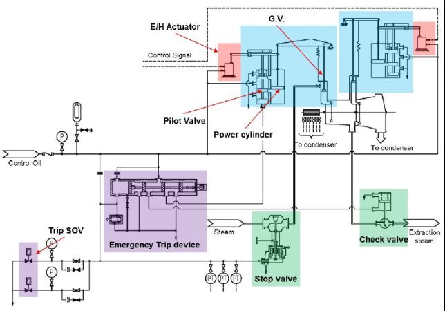
A servo system is designed to control the governing valve of the steam turbine precisely and quickly respond to loss-of-load or emergency. Precise and stable steam valve control directly relates to improved steam turbine speed and load control and reduced system mechanical wear. The conventional servo system is a combination of an E/H Actuator, pilot valve, power cylinder and a complex system of linkages which is used to operate steam turbine control valves.
This article contains excerpts from a paper, “Conventional servo system to direct drive actuators. Why does it matter?” presented by Mayank Jain Engineer, Kenichi Nishiyama and Kyoichi Ikeno of Mitsubishi Heavy Industries Compressor Corporation.

Conventional Servo System[/caption]
The servo systems are expected to run smoothly and precisely for a long period of time but many small factors often lead to failures due to the complexity of the system. Contaminated oil is often a cause for E/H Actuator failure or it may shorten maintenance interval. The complex system of linkages along with bearings (spherical, rod-end and deva-metal) is the major point of failure in the conventional system. The multiple moving parts in the system also make it difficult to analyze and find the root cause of the failures. The cause of failures of linkages varies from high pedestal vibration or high bearing loads to small factors such as improper clearances. A
E/H Actuator: An electrically controlled hydraulic amplifier/actuator which converts electrical signal to a proportional linear/rotary output shaft position to control the flow of steam to a prime mover.
Power Cylinder: A mechanical device which uses the hydraulic oil pressure to provide the necessary force in a linear motion required to operate the Governing valves.
Pilot Valve: A device used to supply hydraulic oil to the power cylinder depending on the movement of E/H Actuator linkages.
The electro-hydraulic actuator converts an electrical signal to linear/rotary shaft output which can be used to drive a steam valve but the required force to move a steam valve is often very high when compared to the output force of an actuator. Small condensate turbines typically don’t need the servo system and an E/H Actuator unit alone can provide the desired motion and force. In medium to large turbines, the E/H actuator alone is insufficient.
When a control signal to increase the steam flow is received by an E/H actuator, the actuator shaft moves in a pre-decided direction and causes movement in the pilot valve shaft. This drives the pilot valve to supply control oil to the power cylinder. The supplied oil creates a pressure difference across the piston of power cylinder which moves the GV linkage. The system of linkages forms a feedback loop which drives the pilot valve until the error between the desired actuator movement and position feedback is zero. The conventional servo also consists of a mechanical trip device which is capable of shutting down the turbine mechanically using a trip button in case of an emergency. A combination of piston, spring force and oil force acts as a set of three way valves. This is used to quickly drain the control oil along with the solenoid valve.
Stroke & G.V. Force: As the turbine size increases, the steam flow to the turbine grows. The governing valves increases in size and so does the required force and stroke to move them. The conventional and direct-drive E/H Actuator have some mechanical limitations on the output force and stroke but the conventional servo system uses a power cylinder driven by an E/H Actuator (pilot valve) and modifying the linkage ratio between them enables the designers to remove any apparent limitation on force and stroke.
Input Power: This is one of those factors which won’t affect the performance of a system unless there are fluctuations/ripples in the power supply. For conventional servo, input power supply is not needed to drive the E/H Actuator so there are no hassles of heavy electric wiring.
Mechanical Trip Cartridge: A completely mechanical device with a trip button which can shut down the Turbine even if all the electronic equipment fails. It can be used with servo that uses control oil to provide the Actuating Force with the help of pilot valve and power cylinder.
Slew rate: One of the most important factors of a servo system is its ability to quickly shut down the steam valve in case of an emergency. The trip time of GV in case of a conventional servo will be same as the time taken by E/H Actuator to close. The conventional E/H Actuator can have trip times as low as 0.2-0.3 sec.
Determining the reliability of a system becomes a challenging task when it involves multiple devices and moving parts. Same is the case in a conventional servo system which has multiple linkages and bearings apart from other components. The problems associated with servo range from oil contamination, hunching, calibration issues, incorrect tolerances and so on. Linkages: To transfer the motion from E/H Actuator to the GV valve with a feedback loop, a numbers of linkages are used. As shown in Figure 4, various components of the system accounts for numbers of failure.
A rod-end bearing is used to connect the GV rod to the Lever and a tight tolerance to keep the components aligned and to minimize the play. Deva Metal, a self-lubricating bearing is used between Lever and connector to provide a frictionless movement between them. Spherical bearings are also used at various parts. Bearing selection for a particular application is sometimes tricky due to availability of various types of bearings. The selection of a bearing depends on the nature of the load, radial and axial force, bearing material, operating conditions among other factors.