SEMI-CLOSED RECUPERATED CYCLE (SCRC) WITH WET COMPRESSION
THE PREDICTED EFFICIENCY OF SCRC IS EQUIVALENT TO A GAS TURBINE COMBINED CYCLE PLANT, WHILE OPERATING FLEXIBILITY EXCEEDS IT WITH SMALLER EQUIPMENT AT THE SAME POWER OUTPUT
BY HANS E. WETTSTEIN

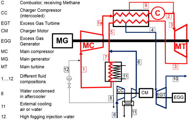
Figure 1
The semi-closed recuperated cycle (SCRC) is a supercharged recuperated gas turbine. It typically involves two compressors with intercooling. However, the intercooled main compressor can be replaced by a compressor with high fogging (wet compression). This permits a thermal efficiency gain by up to 3% while avoiding a bottoming cycle. Part-load operation can be made by reducing supercharging pressure instead of temperature. Thermal transients leading to hot part life consumption can therefore be avoided to a large extent. Additionally, the combustor can operate at nearly constant temperature at low part load with corresponding low emissions. This approach has the potential to add more flexibility in comparison to gas turbine combined cycle plants (GTCC). In this respect, SCRC is better suited for arid and hot environments than GTCC technology. The predicted efficiency of a SCRC will be equivalent to a GTCC, while operating flexibility exceeds it with smaller equipment related to the same power output.
Figure 1 shows the working principle. The red loop is the supercharged part of the cycle. Ambient air (6) is compressed in the “charger compressor,” which is driven by an electric motor allowing variable speed. This fresh air is mixed with recirculated exhaust gas (5) coming from the recuperator cold end. The mixture (7) is cooled in the after-cooler, where water (8) is condensed and separated. The cooled fluid (1) is mixed with the fine and evenly distributed high fogging water (12), for which no external make-up water is needed because the condensed water (8) covers it sufficiently. This fluid containing the droplet cloud enters the main compressor and leaves it with the composition (1a). Then it is heated by the exhaust gas in the counter-flow recuperator and passes through the combustor, where methane as a fuel is burnt. The resulting combustion gas (2) is mixed downstream the combustor with the cooling fluid (9) forming the mixed gas (3) entering the main turbine (this is a well-working simplification for the cycle calculation as used in gas turbine technology, according to ISO standards. The cooling fluid is distributed to different consumers in both the combustor and turbine and finally discharged into the main flow path). The main turbine drives the main compressor and the main generator via a single shaft. The turbine exhaust gas (3) passes through the recuperator while heating up the pressurized fluid (1a). Within the recuperator it is split into the excess gas (4) and the before-mentioned recirculated fluid (5). The excess gas (4) is expanded to ambient (10) in the excess gas turbine driving an extra generator with preferably variable speed.
The corresponding difference of the excess gas turbine power and charging compressor power is positive in steady state operation or during a downward net power load ramp, but it can become negative in the case of a fast upward net power ramp. This difference forms the minor part of the SCRC power output. The application of wet compression allows a higher heat sink temperature with the option of external dry cooling with a marginal loss of thermal efficiency. Due to the supercharging in closed cycles, SCRC can achieve a higher power density with smaller components than any other system. It is directly air breathing and only based on commercially existing GT technology. Instead of temperature control as in open cycle GT’s, inventory control of the power output allows flexible operation with lower life consumption of the hot parts associated with lower maintenance cost ($/kWh).
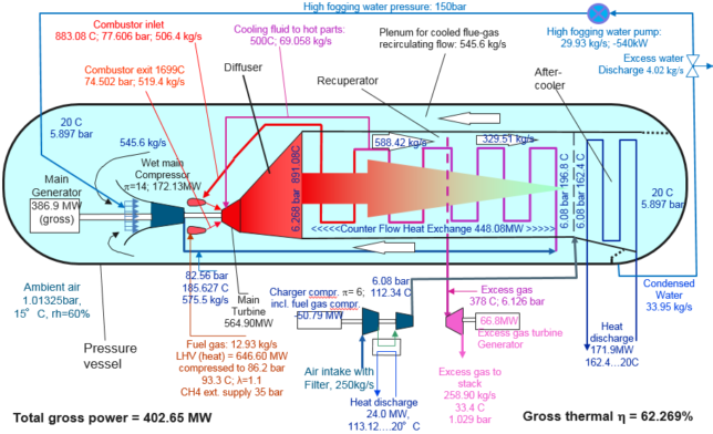
High fogging in the main compressor enables a lower compressor exit temperature at a higher pressure ratio with less complexity than intercooling. The steam content in the flue gas implies a higher power density. Water can easily be recycled because it is condensed at the supercharged pressure level. This water and steam circulation acts like an integrated high-temperature steam cycle (Figure 2).

Figure 2:
Managing upward load ramps means filling the pressurized volumes of the intercooler, the recuperator and the aftercooler. This requires operation of the charger compressor with the highest possible mass flow rate. The charger compressor should be equipped with Variable Inlet Guide Vanes (VIGVs) and a speed controllable motor without coupling to the excess gas turbine. At the same time, the flow through the excess gas turbine should be reduced to the minimum possible amount, or even stopped during the ramp time by an extra valve. A design of the charger compressor with a maximal inlet mass flow rate above the base load value could help to accelerate the filling process. Managing downward load ramps means discharging the pressurized volumes of the intercooler, recuperator and aftercooler, allowing for the fastest and most efficient operation of the excess gas turbine with the highest possible swallowing capacity. It should therefore best be equipped with VIGVs and an extra speed controllable generator without mechanic coupling to the charger compressor. At the same time operation of the charger compressor should be reduced to the minimum possible or even interrupted during the ramp time by using an appropriate valve, which may be a non-return valve or flap.
Replacing the intercooled main compressor with a single compressor with high fogging water injection improves overall thermal efficiency to above 60%. It also boosts power density to over 1,600 kJ/kg combustion air compared to below 800 kJ/kg for the most advanced GTCC’s. The wet compressed SCRC allows a higher heat sink temperature than a GTCC with the option of dry cooling. It does not depend on an external source of make-up water. The operating flexibility of the SCRC concept combined with low cost make it attractive for cases where callable power is needed from a hydrocarbon fuel while high efficiency is needed at low part load. This is an opportunity for grid frequency support.
The absence of an extra bottoming cycle, relatively small turbomachinery and high-power density represent simplicity and a smaller footprint. Smaller SCRC implementations have a high potential for combined heat and power applications and for naval drives. The technologies needed for developing SCRC are all available within existing capabilities.
Author: Dr. Hans E. Wettstein is an Independent Consultant living in Switzerland. For more technical detail concerning SCRC, see his paper Semi-Closed Recuperated Cycle With Wet Compression (GT2017-63375), presented at the 2017 Turbomachinery Expo, or email hans.e.wettstein@bluewin.ch

.png&w=3840&q=75)

.png&w=3840&q=75)


.png&w=3840&q=75)


.png&w=3840&q=75)