TPS 2024: Industrial Gas Turbines and Bottoming Cycles
Session speakers offer an analysis of gas turbines, including their working principles, thermodynamics, condition monitoring and maintenance, and bottom-cycle performance.
On Tuesday afternoon at TPS 2024, speakers from Elliott Group and RKSBenergy held a tutorial, Performance of Industrial Gas Turbines and Bottoming Cycles. Karl Wygant, Senior Manager at Elliott Group, Klaus Brun, Director of Global R&D at Elliott Group, and Rainer Kurz, Principal of RKSBenergy, discussed control strategies and performance characteristics for the engine compressor, combustor, and turbine section.
In addition to covering energy flow concepts between turbine components, the panel outlined control concepts for single- and two-shaft machines, driving generators, compressors, and pumps. Bottoming cycle performance is also discussed, with methods to use performance data for trending and comparison analyses.
Gas Turbines: The Basics
Kurz kicked off the session by outlining the benefits and basic working principles of industrial gas turbines. In terms of benefits, these turbines offer high-power density and efficiency with a low-emissions profile, in addition to attractive maintenance options that enable lower cost of ownership over asset lifetime. Considering these characteristics, a variety of industries deployed gas turbines to provide reliable, often continuous power throughout history.
“When we look at industrial applications [for gas turbines], we often see power generation, compressor driving, and offshore applications,” said Kurz. “The Swiss had the first gas turbine in industrial use for power generation. This gas turbine was designed by Brown Boveri Corporation in a simple-cycle configuration at 4 MW, but has a unique design compared to what we see today.”
Following the brief historical context, Kurz clarified that, regardless of model or application, all gas turbines contain the same three components: a compressor, combustor, and turbine section. The machinery can be divided among single- and two-shaft designs, with single-shaft engines maintaining constant air flow and compressor power at the expense of flexibility and decreased exhaust temperature.
According to Kurz, two-shaft engines are optimal for different load requirements: “Why would I go through the effort to build a machine with two turbine sections? I can set the load, or power that the turbine uses, independently of the driven equipment. Theoretically, you can run the gas producer section to full load before the driven equipment starts to move because it’s not mechanically coupled.”


Rainer Kurz addressing how the driven load impacts power turbine speed.
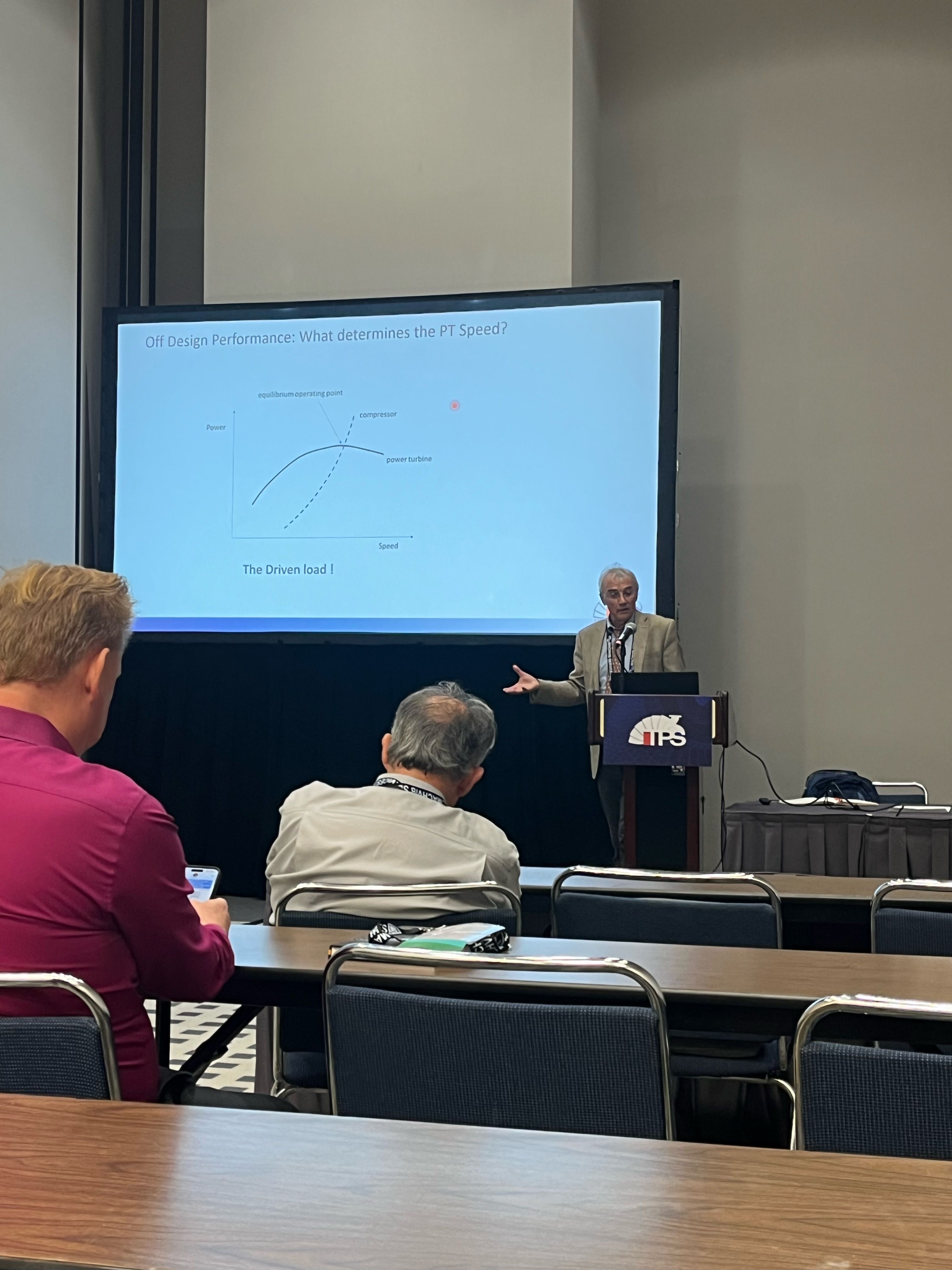
The compressor increases the working fluid pressure, after which fuel is injected into compressed air to increase temperature; then, hot exhaust gas is expanded through the gas producer turbine section to drive the compressor. Leftover energy, in the form of temperature and pressure, flows through the power turbine to run driven equipment.
The turbine’s primary control system ensures that the components work in tandem while avoiding damaging, potentially unsafe operating conditions. For example, systems can control rotors, limit firing temperatures, and trigger an alarm or shutdown if vibrations exceed a particular set point. Additional control methods govern engine speed and pressures.
“There are two types of control for any gas turbine,” said Kurz. “The overriding control ensures you don’t exceed the maximum firing temperature, limits engine speed below the design point, and watches over the engine to keep operation within a parameter box. As long as you stay in the box, process control kicks in to provide the fuel flow needed to maintain power turbine speed and discharge pressure.”
Thermodynamics
Brun led the discussion on gas turbine thermodynamics, which began with descriptions of both enthalpy and entropy. “Enthalpy has many definitions, but from the easiest perspective it’s energy per unit/mass or how much energy you have in the process fluid, which is air in a gas turbine and water in a steam turbine. Entropy can be described as the second law of thermodynamics. If entropy is very high, you have a lot of losses in the system.”
Gas turbine thermodynamic cycles are typically based on the Brayton cycle, which consists of four main processes:
- Isentropic Compression: The working fluid (usually air) is compressed in a compressor, increasing its pressure and temperature.
- Constant Pressure Heat Addition: The compressed air is heated in a combustion chamber by burning fuel, increasing its temperature at constant pressure.
- Isentropic Expansion: The hot, high-pressure gas expands through a turbine, producing mechanical work and decreasing its temperature and pressure.
- Constant Pressure Heat Rejection: The expanded gas is cooled in a heat exchanger (if present), rejecting heat to the surroundings at constant pressure.
Bottoming Cycles
Wygant closed out the tutorial by highlighting the three most common bottoming cycles for industrial gas turbines: the Steam Rankine, Organic Rankine, and Closed Brayton cycles.
The Steam Rankine cycle uses water or steam as the working fluid—waste heat is used to boil water into steam, which drives the turbine to generate electricity. This cycle is less efficient at lower temperatures due to water’s high boiling point.
Organic Rankine Cycles use organic fluids, such as hydrocarbons and refrigerants, in a similar process to the aforementioned steam cycle. With a lower boiling point working fluid, it allows for efficient operation at lower temperatures, flexible design, and a wider range of applicable fluids.
Lastly, the Closed Brayton Cycle uses gas as its working fluid—waste heat is used to heat a gas, which expands through a turbine to generate electricity. The gas is then compressed and the cycle repeats. It maintains high efficiency at high temperatures, potential for combined cycle applications (with a gas turbine), and relatively simple design.


