TURBINE CONTROL UPGRADES IN AGING PLANTS
AS WELL AS ANALOG SYSTEMS, OLDER DIGITAL CONTROLS MAY REQUIRE REPLACEMENT
Aging control systems pose maintenance and operational challenges to operators. As many of the companies that built older systems were located overseas, availability of components can add to replacement cost and extend downtime. In the worst case scenario, obsolete parts either have to be fabricated or a compatible replacement found.
Additionally, few operators and engineers know how to properly maintain these systems. That is why even reliable older systems are being evaluated for replacement — they have effectively become a black box to the technicians and engineers that service and repair them.
But it is not just analog controllers that may be problematic. During the 1990s, many analog controls were replaced by digital systems. However, those early digital systems still had analog input and output interfaces that were susceptible to noise or deterioration.
Today, cogeneration facilities are being engineered with reliable control systems that can manage key processes, such as steam header pressure, bus voltage and voltampere reactive (VAR) import.
Controlling these inputs would allow a two-turbine facility to manipulate varying loads in a constant operator-set ratio. Both units could be loaded equally or in proportion to operational needs. With earlier systems thiswas not possible, and systems often implemented the power rate without operator intervention and without setting new peak power requirements.
Loss of tie-line power
Many plants have enough internal generating capacity to be able to maintain plant power in the event of a complete loss of utility power. Typically there would be a required reduction or loss of plant production capacity until the utility power returned and the plant was re-synchronized to that power. During this time, the on-site steam plant and steam turbine driven generators would still remain in operation.
A scenario familiar to some cogeneration facilities with older control systems, for instance, is the sequence of events leading to a loss of power originating fromeither an interruption of service from the utility orwithin the cogeneration plant itself.Assuming the facility supplies only part of the power required to sustain production processes, a loss of tie-line power would mean the generators onsite are instantaneously overloaded.
By implementing a new load-shedding control scheme with the ability to react initially by quickly shedding a block of load similar in size to the power furnished by the utility feeder, a possible sustainable balance can be achieved. The second stage of the loadshedding scheme would be a generator based on the combined proportional level of under frequency and time duration that would again trigger more load-shedding if required.
The goal is to quickly reduce the electrical load such that it goes belowwhat is required to balance the steamheat sink energy against electrical generation, and if the turbine control system is capable, the governor starts gaining control and stabilizing the steam turbines. Given the required response time, a control system must be able to respond immediately and without human intervention to avert the above scenario.
Planning for the loss of utility tie-line, therefore, must be programmed and tested using the facility control system. The key factors in this control system are the turbine governor that automatically transfers speed/frequency control, and the generator excitation system that is responsible for switching control modes into bus voltage control.
Governor and excitation systems
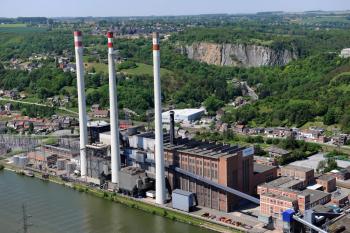
A pulp mill in western Canada had been experiencing many of the above challenges.The facilitywas running two steamturbines, each capable of generating 32 MW of power or 87% of the total power required for the facility (Figure).
To sustain the facility during a loss of utility power, it needed to replace turbine control systems dating back to the 1960s. The mill selected Invensys to retrofit the turbine governor, the excitation system and generator protection systems.
A critical requirement was to have no single point of failure. If the steam plant was to suddenly lose power, a cascade of issues would occur. The recovery boilers’ chemical processes would be upset, the reheating of the chemical process and cleaning of the smelt out of the boilers would take a considerable amount of time, and other boilers would have to be purged.
These and other technical objectives required that the controls be TripleModular Redundant (TMR). In addition, the systemneeded to survive a loss of tie-line power and re-synchronize when the local utility power was re-established, allow dynamic MW and MVAR load division, and to recover power by utilizing the mill process heat sink while controlling header pressures.
The system chosen included two bridges, controlled by a digitally- based voltage regulator that is fault tolerant and repairable online, as well as a “manual” regulator.
Shortly after installation, the mill lost utility power yet successfully maintained a power and steam balance and avoided a shutdown. Complexity had been reduced for the operator. Startup and synchronizing is usually a one-button operation, and downtime has dropped dramatically.
Author
David R. Brown is a Consulting Application Engineer at Invensys Operations Management specializing in turbomachinery and generator controls. He holds three U.S. patents for turbomachinery control technology. Invensys Operations Management provides automation and information technology, systems, software solutions, services and consulting to. For more information call 888.869.0059 or email contact@Invensys.com
Newsletter
Power your knowledge with the latest in turbine technology, engineering advances, and energy solutions—subscribe to Turbomachinery International today.

