Turbines or Engines?
SELECTION DEPENDS ON USER REQUIREMENTS AND APPLICATION
The use of natural gas as the fuel of choice for power generation suggests two possible driver technologies: gas turbines (GTs) and reciprocating gas engines (REs). Due to the range of output available, a 230 MW plant might consist of 13 to 25 RE units, or 1 x 230 MW GTs through to 16 x 15 MW GT units.
The choice depends upon the relative importance of the various drivers of the power plant. These include cost of generation, availability, start-up time, fuel requirements, back-up fuel requirements, capital investment, cycling capability, footprint, heat requirement, weight and more. And virtually every application is unique and involves a different set of drivers.
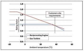
The prime movers (GTs or REs) for a plant produce a maximum power that is dependent upon the ambient temperature; this is defined by the rating line. Figure 1 shows example rating lines for a typical GT and RE, both drivers showing a “flat rating” region at lower ambient temperatures, although for the RE this occurs at a higher ambient temperature than for the GT.

Figure 1: Power output vs. temperature showing rating line for GT and RE[/caption]
It is therefore important that the site’s power requirements are considered across the entire ambient temperature range. In most cases the limiting power will be at high ambient temperatures and hence particular focus should be given to operation in these conditions. The example rating curves in Figure 1 are shown for a site with a maximum ambient temperature of 38ºC. It can be seen that, with a GT, significant extra power can be generated at lower ambient temperatures. In many grid type applications this can be an advantage.
Rating lines are defined by mechanical or thermal limits. For the GT, maximum power is often defined by maximum component temperatures in the turbine (the sloping part of the rating line) and the shaft mechanical design or the generator frame size (the flat part of the rating line). For the RE, the power is often defined by the maximum allowable cooling water temperature (sloping line) and the shaft mechanical design or the generator frame size (flat line).
Power plant efficiency is an important consideration as it is a major driver of overall profitability. However, there are also other considerations that must be accounted for in the profitability equation, as are discussed below. In some cases, though, particularly plants required for back-up, the importance of efficiency diminishes in favor of other parameters related to operational flexibility.
Electrical efficiency

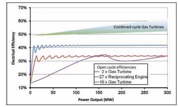
Figure 2 shows examples of efficiencies for multiple small GTs and REs, and single or dual gas turbines with and without combined cycle. The highest electrical efficiencies are achieved by GTs in combined cycle configuration.
Even with smaller GTs in combined cycle configuration, electrical efficiencies in excess of 50% can be achieved. Simple cycle RE electrical efficiency reaches 48% in some cases and, in a combined cycle configuration, this can be raised further without reaching the levels of GTCC. However, simple cycle GT efficiency is lower than REs; the most efficient GTs achieve about 40%.
One further factor has to be taken into account: the change in the power production mix is requiring gas-fueled power plants to be flexible and operate more frequently at part load. In Figure 2, multiple unit plants at part load have an advantage in efficiency over single- or dual-unit GT plants.
So far we have mainly considered a power plant producing electrical power only.
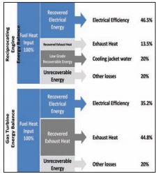
However, overall efficiencies and maximized savings can be achieved with the installation of a cogeneration plant. Cogeneration requires a heat load, and this can be an industrial process or a cooling or heating requirement for a building complex. Heat can be provided from the waste heat of the RE or GT. By using waste heat from power generation, energy efficiencies of over 70% can be accomplished, with some installations achieving around 90% overall energy efficiency. However, there are differences between the scope of equipment and the amount of heat available.
For the GT, all heat is in the exhaust gas and is often at high temperature. In addition, the exhaust gas contains significant oxygen and hence fuel can be burnt in the gas to raise the temperature further — a technique known as supplementary firing. For the RE, the heat emerges at a variety of places, typically in the exhaust gas, the lube oil and the cooling water. To use all the heat available from a GT, it only requires a waste heat recovery unit (WHRU). But, to use all the heat from an RE, a WHRU in the exhaust gas is required as well as heat exchangers on both the lube oil and the cooling water circuits.

Figure 3: Available heat for cogeneration[/caption]
Figure 3 shows the amount of heat typically available from each technology. To use all the heat from an RE, there must be a low temperature heat supply (e.g., hot water).
Now let us take a look at the different factors that influence plant operability, beginning with availability (defined as the amount of time, during a year that a plant is available to produce power). This takes into account both planned and unplanned downtime.
When considering single unit installations, then, plans must be put in place for when the unit is not available. This can mean either a total plant shut-down period or provision of the heat and power via other means(grid connection and a packaged boiler, for example). In cases where non-availability cannot be tolerated (for example on an oil platform) a 1+1 or 2+1 configuration will be adopted where extra units are purchased to ensure near to 100% availability.
Generally REs achieve availability in the region of 92%, whereas GTs regularly achieve in excess of 97%. This 5% difference is equivalent to 18 days per year of operation. In single unit plants, this equates to more downtime, or more cost associated with using external supplies of electricity and heat. In multiple unit plants, to achieve the same availability on a 20-unit GT plant, the RE plant will require 21 units.
Dual fuel capabilities should also be considered. Many power plants save on costs by accepting an interruptible supply contract on gas fuel. However, provision needs to be made for when the gas fuel supply is cut off.
Many plants provision for loss of gas supply, particularly the smaller size, by installing a liquid fuel capability and purchasing an RE or GT capable of running on either fuel. For GTs <15 MW, a dual fuel capability is requested in upwards of 30% of applications.
Dual fuel GTs can operate on 100% liquid or 100% gas fuel and changing between fuels is done without any interruption to operation. Dual fuel REs, however, cannot operate on 100% gas fuel as a small amount of pilot liquid fuel is always required. This liquid pilot can be as high as 2% of fuel flow and, as liquid fuel is significantly more expensive than gas fuel in many locations around the world, this small liquid pilot flow can have a significant effect on project economics. Changeover times between fuels, and the ability to change fuels at full load should also be considered, as dual fuel REs usually require load to be reduced to around 80% of full load when transferring from liquid fuel to gas fuel. Start time can also exert an influence upon plant operability.
Start time for a GT and RE can be divided into three phases; preparation, starting, and loading. The preparation phase consists of valve and system checks, purging of ducting, and heating of casings and lube oil to the required temperature. Overall start time can be reduced if the engine is held in a ready state.
However, doing this requires electrical power for both engine turning and oil and casing heating. GTs only require the lube oil to be at or above 20°C. REs, on the other hand, require the cylinder heads to be at or above 60°C; this is achieved by heating and circulating cooling water and, from a start point at 20°C, can take around 10 hours and requires up to 300 kW of electrical power. Once at temperature, a large RE might require upwards of 100 kW to maintain this temperature.
Startup
In general, the starting and loading phases for GTs and REs take similar times, usually on the order of 3-to-10 minutes. Historically, the start time for a combined cycle plant has been longer than that for the GT or RE alone. However, these times have been reduced and now a 500 MW combined cycle plant can be started to full power in 30 minutes.
In Figure 2, we discussed the efficiency characteristics and comparisons between a single, dual and a multiple unit plant. If this plot is now considered in relation to load application, it becomes clear that during load application in multiple unit plants, the engines must be started and that this will limit load application rates. Different technologies have different step load acceptance (and rejection) characteristics which must be considered. Power consumed in stand-by mode must be taken into account in the efficiency sum.
Emissions, too, form an important element in any comparison. NOx, CO and unburnt hydrocarbons (UHC) are often regulated. Even those areas where no regulations exist, the financing of projects by companies within regulated regions often drives projects to implement emissions restrictions.
In most cases, available prime movers satisfy existing regulations. However, without using any secondary means of reducing emissions, the emissions from an RE are significantly higher than those from a GT.

Table 1: Available heat for cogeneration[/caption]
Table 1 compares nominal emissions using currently available technology without using a secondary means of emissions reduction. In many places around the world, these emissions levels satisfy the regulations for NOx, but for CO and UHC the RE will often require a secondary reduction technique; usually an oxidation catalyst in the exhaust.
But there are areas in the world where these emissions figures are not acceptable. Many GTs can operate with “single digit” NOx levels without a secondary reduction method. This is currently not possible for REs, which tend to use Selective Catalytic Reduction (SCR) comprised of an exhaust catalyst and a reducing agent (ammonia most commonly).
Carbon Dioxide is another emission in the spotlight. CO2 emissions are directly linked to the amount of fuel burnt. This is the reason behind the push towards cogeneration where the largest efficiencies can be reached. It should also be noted that methane, which makes up most of the UHC emissions in Table 1, is twenty times more potent as a greenhouse gas than CO2. Therefore an emission of 1,300 pmmV UHC (0.13%) is equivalent to another 2% of CO2.
GTs and REs both require auxiliary services to be able to start and operate. Provision of these services can have an effect on power plant operation as well as management logistics and overall footprint required. Hence, it is vital that these are fully considered in design. These auxiliaries include lube oil, fuel supply, compressed air supply and water supply.
All REs and GTs above 5 MW require lube oil. However, there are differences in consumption rates between the two technologies. Fundamentally, the difference is due to the proximity of the lube oil to the combustion process in an RE whereas the lube oil and combustion system in a GT are separate.
A RE consumes oil during operation (requiring regular level checking and topping up) and needs regular oil changes. During operation, for an equivalent output power of around 18 MW, a RE will consume in the region of nine liters per hour, while a GTs hourly consumption is 0.02 liters per hour. This equates to 0.5g consumption per kWh generated for an RE and 0.001g/kWh for a GT.
GTs need gas fuel at higher pressures than REs. GT fuel-supply pressure needs to be over 20 bar, and sometimes higher, whereas many REs can operate at 5 bar. Unless local high-pressure gas supply is available, a GT will need a larger gas compressor than an RE installation.