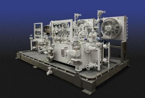
Efficient field flushing prevents equipment damage

One of the most important pre-start-up operations for an auxiliary system is flushing. The object of flushing is to render the entire auxiliary system free of excessive particles that could enter into critical equipment components, thus causing significant equipment damage.
To ensure efficient field flushing preparation, understanding of the entire system and monitoring of flushing operations is required. A schematic showing the entire auxiliary system must be reviewed prior to establishing the flushing procedure.
Each system will include an auxiliary system console, inter-connecting piping, unit piping, and drain piping. In the case of liquid seal systems, drain side components will also be included (automatic seal oil drainers degassing tanks, etc.). Review of the specific system is essential to determine the location of flushing screens and sequence of the flushing operation.
Flushing without duplication
The basic philosophy of any flushing system should be to avoid duplication in flushing that merely prolongs the action and minimizes the effect. Therefore, any possible pre-cleaning prior to installation is advisable. As an example, all interconnecting piping should undergo thorough cleaning when received in the field. Once clean, the piping should be treated in ‘white room conditions’ prior to installation.
Any special care taken at this time will significantly reduce flushing time. Considering the volume of interconnecting pipe, its cleanliness is a significant contributor to minimizing flushing times. Since the majority of interconnecting pipe volume exists in atmospheric drain pipe, any dirt in the unwetted portion of the pipe will cause significant problems during the flushing operation, since these pipes are not pressurized.
Many flushing operations have experienced setbacks as the result of a high liquid level in the drain lines, which causes a significant amount of debris to appear in the flushing screens when the system appeared to be ready for acceptance.
Using sequential flushing loops
Once the entire system is installed, flushing should proceed in sequence using flushing loops. Begin at the pumps with the pump loop (pumps through relief valves), and proceed to the bypass pump loop, the cooler loop, etc., until the console is relatively clean.
This exercise will ensure the removal of large amounts of debris and minimize the possibility of flushing screen breakage. It must be noted that any special care taken from the point of manufacture to start-up in terms of preservation will be appreciated at this point.
Hints that signal change
If possible, a pressure tap should be present upstream of flushing screens to determine changes in pressure, thereby signaling the need to change screens. The specific flushing procedure will detail screen location, size and changing times.
Oil system flushes during construction and turnarounds can be very long (weeks or months) and subject the plant to lost revenue by postponing plant start-ups. The ‘best practice’ of flush procedure contained in the supporting information, developed by Merle Crane – consultant, incorporates seldom-used procedures (nitrogen bubbling, oil cooler isolation and drain line monitoring) that reduces flushing times to less than a week if followed completely.
In addition, unlike most flushing procedures, it will produce an oil system that will not require frequent on line filter changeovers or expose the machinery components to lower MTBFs.
Poorly designed and/or implemented oil system field flushes result in significantly extended start-up times and usually are not followed completely after the original flush schedule time has been exceeded. This ‘best practice’ oil flush procedure has been used since the mid-1980s.