Electric drive motors in turbomachinery

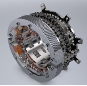
The split Rosenberry hub provides thermal stability during starting, reliable synchronizing and speeds up to 2,160rpm[/caption]
Since the early seventies there has been a move toward the use of electrical drives in turbomachinery. The logic is simple. Why burn a part of the needed hydrocarbons when electric power can be purchased to save on feedstock.For larger drives,the synchronous motor offers cost and efficiency benefits over induction counterparts. They offer a fixed speed for grid supply as well as stability of speed that is ideal for fans, blowers, centrifugal pumps and compressors.
Any increase in power factor raises supply capacity, efficiency and improves the operating characteristics of the electrical system. Overexciting the field means the motor can be used to correct the power factor of lagging load such as transformers and induction motors in a plant. Improvements in electro-mechanical design have allowed larger synchronous motors to be developed and manufactured, such as GEC’s 59,000HP (44MW) 4-pole 11kV.
The parallel development of solid state power electronics has allowed the introduction of reliable rotating diode rectifier bridges and the inclusion of brushless excitation as an integrated element of the motor assembly. This removes the need for slip rings and lowers maintenance requirements.
These brushless excitation designs mean that the motor and the compressor train can run for longer between outages.This enables better integration into the compressor’s maintenance regime. Trains can run for over five years between outages.Many owners and operators are pushing for longer runtimes to maintain operational efficiency across the production facility.
Start up
In an induction motor, the stator is energised from the grid, creating a rotating magnetic field. This induces an alternating current through the bars, producing nearly 10 times the current compared to when it is in a fully loaded state. This induced current flow creates a repulsion field between the rotor and stator that is sufficient to accelerate the rotor. As the rotor nears synchronous speed, the effect decays until a steady speed is reached, just below synchronous speed. This is referred to as slip speed.
In a synchronous motor, the acceleration to slip speed is identical.However, currents are induced in the field winding instead of a copper cage. To protect the field during this phase of the start-up and to include the starting resistor to improve starting torque,extra solid state switching thyristor devices are added onto the field circuit.This allows the induced field currents to flow safely.
A synchronous motor differs from an induction motor, by the addition of a rotating DC field winding. As the exciter is an AC generator, its output must be converted to DC by a diode bridge.The DC current in the field converts the rotor into a giant electro magnet. Once the field winding is excited, the magnetic field generated will lock into synchronism with the stator field.
Care is needed to align the rotor magnetic field with the stator field to prevent a ‘mal-synch’ event where the rotor will violently change speed to catch up with, or slow down, to synchronise with the stator. These events can cause torsional shear failures, to control this final stage a synchronising unit is used.
To move from an asynchronous to synchronous operation, the exciter supply has to be allowed to pass into the diode bridge and then the field. Once the rotor is near to the slip speed and the acceleration rate drops off, excitation is applied by energising the exciter stator field from the controlling Auto-Voltage Regulator.
Starting components are subjected to high centrifugal loads along with heat and electrical losses. Over time, they wear out. Accumulation of contamination and minute particle debris on heat sinks and components over time increases the component operating temperature. The electrical insulation also degrades quicker with increased heat or excessive voltage and current demands. Downtime is often due to components,which cost very little compared to lost production time. Spare diodes, thyristors, bearings and seals should be in good supply.

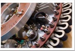
Retrofits to the electric motor rectifier can extend lifespan and prevent a costly outage of a turbomachinery train[/caption]
In any evaluation of turbomachinery, then, don’t forget to look into the state of the electrical prime mover. Isolate motor problems before failure occurs. Watch out for obsolescent parts that may delay outages. Retrofitting the rectifier is a good way to overcome obsolescence and extend the operational life of a motor drive. The split Rosenberryhub, for example, gives greater freedom as to where it can be mounted on the motor. It has been specified to run for more than 1,000,000 hours. The hub weighs 250 kg, is 400mm in length and uses conservatively rated components upto 600Adc and 750Vdc and designed for safe and reliable synchronizing.
Tony Croucher is the Engineering Technical Services Manager at Quartzelec, an independent electrical services provider based in the UK that specializes in rotating electrical machines.Quartzeleccan design, manufacture, repair, refurbish and rewind large, project critical motors and generators.