Failures in babbit bearings
Below are excerpts from a paper titled, ‘Babbitted bearing health assessment’ presented at this year’s Middle East Turbomachinery Symposium by John K. Whalen of John Crane, Thomas D Hess Jr of DuPont Engineering Research & Technology Rotating Machinery Group, Jim Allen Nova Chemicals Corporation, Jack Craighton, Schneider Electric.
There are dozens of ways babbit bearings can fail. Some of the common failure modes are babbitt fatigue, babbitt wiping due to rotor to stator contact, babbitt flow due to high operating temperatures, foreign particle damage, varnish build up, electrostatic discharge damage (frosting), electromagnetic discharge damage (spark tracks), oil “burn” or additive plating due to high temperatures, loss of bond between babbitt and base metal, chemical attack, pivot wear in tilting pad bearings, unloaded pad flutter and cavitation damage.
Low speed “wiping” and fatigue
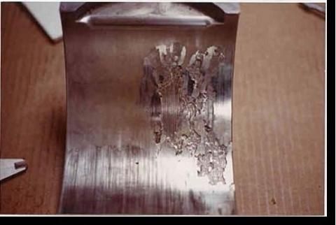
The adjoining figure shows a bearing
that exhibits slight low-speed wiping coupled with at-speed fatigue damage
brought on by bearing to journal misalignment.
Here we see that the bottom portion of this bearing shows an even wipe (or polish) pattern from low speed operation (operating in the boundary lubrication regime). We also see fatigue damage; however, this is presenting itself only on the right side of the bearing – indicating that the bearing became misaligned once up to speed.
When a sleeve bearing is operating in the full film lubrication regime, a film of oil separates the journal from the bearing and the hydrodynamics pressure profile puts the operating position of the journal off at an attitude angle. That is why the babbitt damage is downstream from bottom dead center.
The user theorized that as the machine became loaded and thermally soaked that the bearing pedestal moved axially, actually tilting, thereby edge loading the bearing. This edge loading resulted in basically half the bearing taking the load causing high babbitt temperature and high peak film pressure.
Babbitt fatigue is caused by dynamic loads on the babbitt surface. Typically in bearings of this type the dynamic loads are caused by vibration and result in peak film pressure fluctuations. Cracks initiate on the babbitt surface and propagate radially towards the bond line. As the cracks get closer to the bond line the strength of the backing material reinforces the babbitt and causes the cracks to turn and spread circumferentially, meeting with other cracks and dislodging pieces of babbitt.
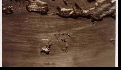
A close up of the babbitt surface (adjoining figure) shows portions of babbitt missing and a section showing only surface cracks.
(Close up of fatigue damage)
Babbitt fatigue strength can be increased by utilizing thinner babbitt (to take advantage of the backing material strength) and by keeping the babbitt temperature low. The effects of these parameters on fatigue strength are based upon dynamic tests with 2000 psi mean load. Obviously, for a running machine, changing babbitt thickness is not an option, but taking steps to reduce temperature and vibration often times are available.
Loss of bond between babbitt and base metal
This is most common when babbitt is applied to copper alloy. Copper is used extensively to reduce bearing operating temperatures by allowing a significantly increased heat transfer coefficient. Most bearing companies use a copper alloy that has good stiffness and strength while still having good heat transfer properties. Figure 3 (below) is a photograph of a sheet of babbitt that came off of a 16” journal pad.
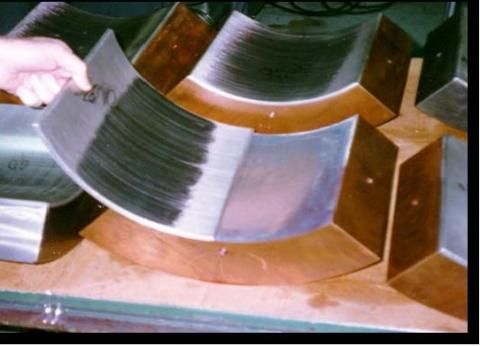
It has been discovered that copper has a strong affinity for tin and this is magnified at elevated temperatures. When babbitt is applied to bearings the process includes a tinning operation so the tin adheres to the base metal and then the babbitt bonds to the tin. Should the tin diffuse into the copper, the bond will become weaker and weaker, and brittle.
(Loss of bond with copper pads)
Oddly enough, this is often times not discovered during normal NDT inspection (such as visual, PT or UT) since the bond is intact, it is just compromised and measures of bond strength are destructive.
It has been discovered that applying a barrier layer prior to babbitting can eliminate this issue. A material must be selected that has good bond strength to copper and the tin will adhere to, while providing a barrier to tin migration into the copper.
This failure mode is not possible to predict with conventional condition monitoring tools. As such, the best way to address this issue is to verify the copper backed bearings, new or repaired, have a proven barrier layer. If there is a question as to whether the barrier layer exists it is recommended that during the next outage this is addressed. Also, while the primary authors company has seen dozens of bearings that have had this problem none of them have failed in service; it is theorized that the brittle bond is not challenged during normal operation.
Electrostatic discharge
It is known that rotors can build up a static charge and this charge will jump to ground through the easiest path available. Preferably, grounding brushes are utilized and these brushes take the charge off the rotor to ground in a controlled way. If there are no grounding brushes or if they are not working properly then this charge can go to ground through the location where the rotor is closest to a grounded stationary part. A pad exhibiting signs of electrostatic discharge is shown in the figure given below.
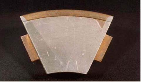
(Thrust pad with electrostatic discharge damage)
Note that with a bearing like this, the point of minimum film thickness is typically on the upper trailing edge as shown. Note that the babbitt has been spark eroded away starting in the minimum film thickness corner and working its way down the pad, as the pad shape changes. This damage can be avoided by ensuring there is adequate grounding.
Pivot wear
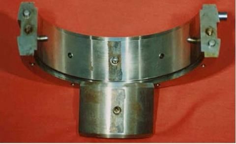
Since pads in tilting pad journal and thrust bearings actually tilt they can exhibit damage at the pivot interface(s) that can affect the performance of the bearing.
(Pivot wear is shown in the adjoining figure)
Tilting Pad Journal (TPJ) bearing outer shell damage can be caused by dynamic load being transmitted across this interface (typically brinnelling damage) and by relative motion of the pad to the shell (typically fretting). Either or both of these wear mechanisms can act to wear the pivot interface which can manifest itself as an “opening” up of the bearing clearance, possible resulting in increased vibration.
One way to detect the possibility of this happening is by monitoring the shaft centerline position for journal bearings and axial position for thrust. If moves are detected and there is no tin found in the oil then one may conclude there is a possibility of pivot wear. For journal bearings this could also be accompanied with increased vibration (due to loss of stiffness and damping with the increased clearance).
This damage can be avoided with a lower stress pivot design and/or control of vibration levels.
Oil coking
From time to time, oil analysis may indicate that the oil is oxidizing and/or an additive package content is diminishing. This could also be accompanied by slight rotor position moves and is usually present when there are elevated temperatures.
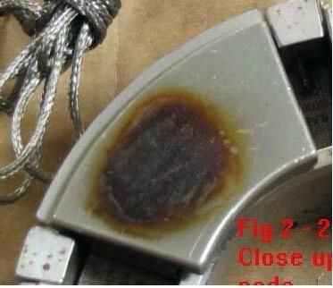
The adjoining figure illustrates this phenomenon. Note that the presence of this “coke” is typically located in the area of the bearing exposed to high film pressure coupled with high operating temperatures; also note that the 75-75 location does seem to represent the most distressed portion of the pad.
(Oil coking)
This damage mechanism can be avoided with careful selection of additive packages, monitoring of oil analysis and control of operating temperature.
Varnish
As mentioned earlier, the formation of varnish on lubricated surfaces has increased over the last 15 years or so as the more highly refined Group II oils have been utilized. At first glance it may appear as though the damage is similar to coking but further analysis will show that varnish deposits can be found on any surface in contact with the oil, high temperatures and pressures are not required.
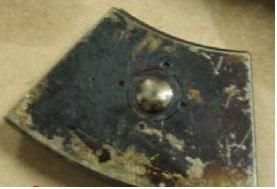
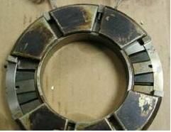
(Varnish formation)
A severe case of varnish formation is depicted in the figures here. Note how the varnish is not isolated to the hot spot of the thrust pads but can be seen on the retainer, links and even the back side of the thrust pads.
This damage can be avoided by being aware of varnish potential as predicted by oil analysis and taking steps to mitigate the phenomena. Signs that you may be experiencing varnish deposits include rotor position changes (due to the deposits getting thicker) and temperature changes due to the insulating behavior of the deposits and the thickness of the deposits resulting in reduced clearances.
Even worse side effects could be found where the oil is used for other purposes in the machine (such as servo valves, etc). In these cases, the tacky varnish coated surfaces can result in “sticky” operation of the components in question.
(John K. Whalen is the Chief Engineer - Bearings for John Crane Engineered Bearings. James “Jim” Allen is a Senior Rotating Equipment Specialist in the Reliability Team for Nova Chemicals, in Red Deer, Alberta. Thomas Hess works in the Rotating Machinery Group for DuPont located in Wilmington, Delaware. John Craighton works for Schneider Electric as a Technical Consultant.)