GE gas turbine LVDTs vs. conventional LVDTs
The Alliance Sensors Group model S1A module, an advanced single channel LVDT signal conditioner, is capable of operating any LVDT currently available. But occasionally, users are confused by unusual LVDT configurations, particularly with regard to the LVDTs used by GE with their gas turbines. This article focuses on how those LVDTs differ from ordinary LVDTs and how to operate them with an S1A module.

To understand th
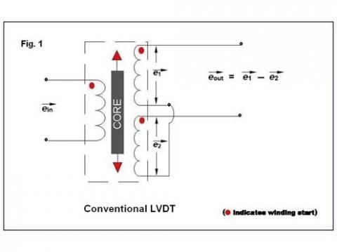
e differences between GE gas turbine LVDTs and conventional LVDTs, it is important to review the characteristics of an ordinary LVDT. Regardless of the actual method of construction used to make it, a conventional LVDT has a primary winding and two identical secondary windings that are often connected in series opposition as shown in Figure 1.
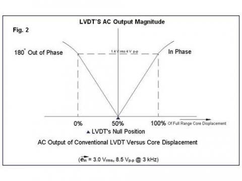
The electrical output of an LVDT as a function of its core's position is shown in Figure 2 below.

Note that the plot of its AC output amplitude versus position shows the classical "V" shape usually associated with an LVDT, with a minimum value called null at the center of its range of motion, and increased output amplitude for core positions on either side of null. Even more important is the fact that the phase relationship of the differential AC output to the primary input voltage shifts abruptly by 180 degrees as the core moves through null. It is this 180 degree phase shift that permits the user to know on which side of null the core is positioned. Voltages and frequency shown are typical of those found in the operation of a conventional LVDT. It is important to note that the actual excitation voltage utilized makes little difference to an LVDT's performance; it is only the excitation frequency that is actually important for proper operation.

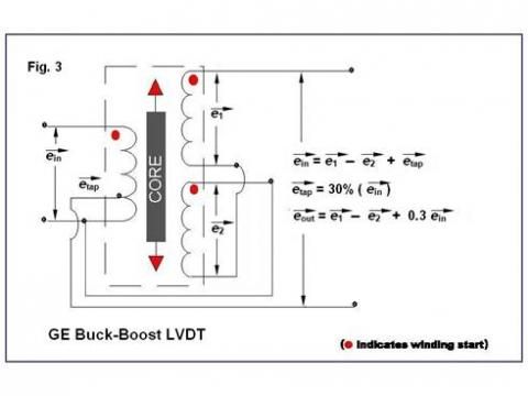
The configuration of the LVDTs used by GE for various position sensing functions on their gas turbines is shown in Figure 3. Although it does not seem to be much different from that of a conventional LVDT, its operation is significantly different. The most obvious difference is the existence of a tap on the pri
mary. It is tempting to view it as a center tap, but it is not a center tap at all. Most often, it is a 30% tap, but, depending on the model, it can sometimes be a 25% tap. The voltages shown are typical of those used by GE, but, as noted above, the device is a transformer and will be functional with whatever voltage is used to operate it. For the sake of clarity, the typical GE values are used for the explanation of how this LVDT works.
This LVDT hookup is generally known as a "Buck-Boost" configuration. As you can see in Figure 3, the voltage appearing at the tap is 30% of the excitation voltage being applied to the LVDTs primary, and is in phase with the primary voltage. The way the windings are connected, this 30% voltage, e tap, is being added to the differential secondary voltage, which consists of e1, which is in phase with the primary voltage to which has been added e2, which is 180 degrees out of phase with the primary voltage. The turns ratio of these GE LVDTs is usually about 5:1, so, with a 7.07 V ACrms input, the full scale secondary output, without the effect of the 30% tap, would be about 1.4 V ACrms, either in phase with the primary excitation, or 180 degrees out of phase with it. However, the 30% tap inserts an additional 2.1 V ACrms that is in phase with the primary excitation that is now added to the voltage already in the secondaries.

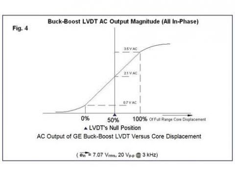
The result is plotted in Figure 4, which shows that the total AC output from this connection of secondaries and the 30% tap is a voltage of 0.7 to 3.5 V ACrms, with no 180 degree phase shift as the LVDT's core moves from one end of range, through null, to the other end of range.
The electronics used by GE requires this unusual AC output, but almost all these "Buck-Boost" LVDTs can be successfully operated with an ASG S1A signal conditioner module by using the proper connection configuration. The first thing is to ignore any connection to the primary tap. Connect the LVDT in a 3-wire configuration as shown in the S1A instruction manual. In this configuration, the high end of the primary is connected to J1-1, the common connection of the primary and the series-connected secondaries is connected to J1-3, and secondaries' output is connected to J1-4. An S1A's 3-wire configuration only applies 1/2 of the usual input voltage to the primary, so it is a good practice to shift jumper J7, or to remove it completely, to increase the excitation output to the LVDT's primary. After this "Buck-Boost" LVDT connection has been completed, the S1A is operated and calibrated in the normal manner shown in the manual.