Measurement of bearing clearance
Bearing clearance is one of the most important parameters in the operation of a bearing. Therefore, it is important to determine the installed clearance along with the bore contour and concentricity to the outside fit diameter. The final bearing clearance is influenced by the contour of the housing into which it is installed, and also by the amount of interference or crush between the bearing shell and the support housing. Proper crush is crucial in the operation of high speed and critical machinery. Improper crush can lead to either a hot bearing or a loose bearing fit.
This article contains excerpts from the paper, “Measurement of bearing clearance” by Fouad Y Zeidan and Bernard S Herbage at the 20the Turbomachinery Symposium in 1991.

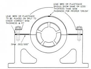
Measurement of Bearing to Housing Fit (Crush).[/caption]
A loose bearing may contribute to synchronous or subsynchronous type vibrations. It is critical that a metal to metal fit to 0.002 in of crush on diameter be maintained for a proper bearing installation. This criterion applies to most thick shell bearings and linings. For thin shell bearings, and in situations where the rigidity of the housing is much greater than that of the bearing liner, the values for crush should be arrived at by consulting with the bearing and equipment manufacturer. What should be guarded against in these cases is excessive crush or a contact stress that could cause local yielding of the material. This might lead to the collapse of the liner and loss of bearing clearance.
A procedure to check bearing crush is illustrated. Place shims of equal thickness (Ts) along both sides of the split lines. Lay a strip of plastigage or lead wire on top of the bearing shell along the shaft axis. Install the bearing cap or strap and tighten all split line bolts. The plastigage or lead wire should indicate a thickness (Tf) equal to or less than the shim thickness used at the split line. The amount of interference (crush) is equal to the difference between the indicated clearance (Tf) and the shim thickness (Ts). A negative value for the crush indicates a loose bearing and the problem has to be rectified by replacing the bearing or using shims around the circumference to maintain an interference fit. Once the desired crush has been obtained, the bearing clearance should be checked again to ensure that the crush is not excessive to the point of significantly reducing the bearing clearance.

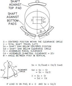
Schematic showing shaft sink between pads[/caption]
A lift check is commonly utilized to accomplish this task. It i s important to recognize that the field lift check is fraught with problems which hinder it from providing an accurate measure of bearing clearance. Therefore, it should be used with caution and mainly to check gross problems and not as a qualifying check for acceptance or rejection of the bearing. Some of the problems encountered in a field lift check are, sticky or uncalibrated dial indicators, a soft foot on the machine, or a flexible housing support.

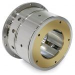
A Waukesha journal bearing[/caption]
Placement of the indicators as well as the means by which the rotor is lifted can significantly influence the outcome of this measurement. The lift check or bump check method shown in Fig 16 can sometimes result in values larger than the specified clearance on certain bearing configurations. This is due to the fact that under static conditions the shaft will sink between the two bottom pads on bearing configurations having a load between pad design and the shaft will rise above the clearance bore at the top of the lift on load-on-pad designs. The shaft sink below the clearance circle is important particularly with the use of end seals on three pad bearings where the shaft sink is 50 percent of the bearing diametral clearance.