Atypical cases during mechanical run test of a centrifugal compressor
Case of probable structural resonance
During a mechanical run test of an axially split centrifugal compressor, polar plots from the rotor’s Y-direction probe showed an unusual pattern for a healthy machine at steady state running condition.
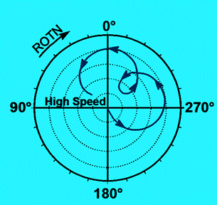
Figure 1 – Loop in shaft Polar Plot
This implied several likely issues:
* A casing resonance affecting the rotor bearing system behavior
* Light infrequent rubs between rotating and stationary components like labyrinth seals can cause an increase in stiffness at one direction. In this case, shaft unfiltered orbit plots did not show any indication of light rubs as the bright spots were not changing by location
* Compressor support problems mainly due to piping layout or looseness in the compressor foot (an indication of different flatness of support)
Assembled clearance and preloads were investigated in a dynamic simulation of the rotor. This concluded that bearing assembly was carried out in accordance with the instructions laid down by the bearing manufacturer.
It became imperative to measure the actual rotor vibration in the direction of the bearing’s principal stiffness. In this case, it was impossible to mount probes in the desired position 90 degrees out of phase with the horizontal and vertical orientation. Therefore, the probes had a 45-degree deviation, a common configuration in rotating machines used in the oil and gas industry (Figure 1).
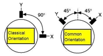
Figure 2: X-Y shaft displacement probe orientation
To display data with respect to a true vertical and horizontal coo
rdinate system, one mu
st rotate the data by the probe’s angular offset from the desired coordinates. Figure 2 shows the effect of compensating for a 45-degree mounting position. Virtual rotation of the probes was carried out using the vibration diagnostic software.
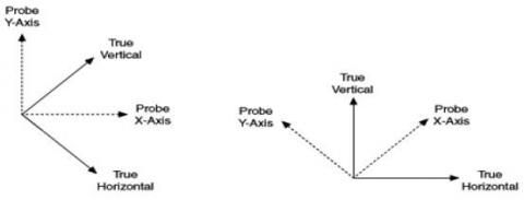
Figure 3: Virtual probe rotation diagram
The machine was started and taken to steady state condition. Polar plots from both probes were plotted. The inner loop was no longer found.
The phase amplitude plots by the X and Y probes showed slightly varying critical speeds with different amplification factors. When the phase amplitude plots were superimposed on graph paper, the distance between the two resonant peaks were not large. The phenomenon was further investigated in detail and it was concluded in the following way with the agreement of the end user.
Due to the axial split configuration of the machine and nozzle orientation, the bearing’s contribution to vertical stiffness was considerably higher than horizontal and the rotor demonstrated two critical speeds with different synchronous amplification factors. This was a case of split resonance in the rotor bearing system. There was no issue of casing resonance and possible light rotor rub based on conclusion drawn after virtual rotation of the X-Y probes.
Resonance that is only present in a single direction can often be indicative of machine support problems. Proper anchoring of piping and grouting of the base frame, therefore, was given higher importance. Lesson learnt: To deal with these issues, a diagnostic tool with a feature for virtual probe rotation should be used to avoid confusion and save time.
Case of High non-synchronous discrete vibration
Clause 4.3.1.3.2 of API 617 7th edition states:
“While the equipment is operating at maximum continuous speed, or other speed required by the test agenda, vibration data shall be acquired to determine amplitudes at frequencies other than synchronous. This data shall cover a frequency range from 0.25 – 8 times the maximum continuous speed. If the amplitude of any discrete, non-synchronous vibration exceeds 20 percent of the allowable vibration as defined in 2.6.8.8 of Chapter 1, the purchaser and the vendor shall mutually agree on requirements for any additional testing and on the equipment’s acceptability.
Clause 2.6.8.8 states:
During the mechanical running test of the machine, assembled with the balanced rotor, operating at its maximum continuous speed or at any other speed within the specified operating speed range, the peak-to-peak amplitude of unfiltered vibration in any plane, measured on the shaft adjacent and relative to each radial bearing, shall not exceed 25 um pk-pk .”
This clause provides a directive to check on probable non-synchronous instability. This clause intelligently helps to identify and mitigate any issue of oil film instability (whirl and whip) during the mechanical run test (MRT).
During the MRT of a centrifugal compressor, it was found that a vibration peak of 3.65 um pk-pk was present at 4406 RPM at machine speed of 12000 RPM. Later on it increased up to 6 um pk-pk while the lube oil supply temperature was increased as per test procedure (Figure 3).
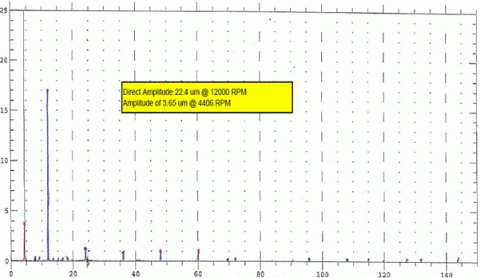
Figure 4: Non-synchronous shaft vibration peak in Spectrum (shown in red)
The value of the non-synchronous vibration peak found was an apparent deviation from API criteria for acceptance. A detailed analysis along with a waterfall spectrum was carried out to find the reason for such vibration.
The frequency of high peak was 0.367X which was quite different from the oil whirl frequency (0.42-0.48X). The test bed train consisted of an 18 MW motor with two different gear boxes to carry out the tests in one test campaign. In between the motor and gear boxes, geared couplings were used at the test bed.
After registering the operating frequencies of all components, a tabular chart was prepared to correlate the non-discrete vibration.
It was discovered that hot oil was causing the bull gear of the gear box to vibrate and this was being transferred to the pinion. This effect directly caused a vibration peak on the compressor shaft at the bull gear’s operating frequency. The detailed spectrum and analysis of the compressor rotor did not show any internal instability of any kind. Even during coast down, a high momentarily peak was observed caused by high train inertia contributed by huge rotational inertia of the motor (Figure 4).
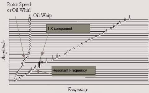
Figure 5: Typical waterfall spectrum
Based on the assumption that the non-synchronous peak was not related to actual train frequencies, the machine will not be operated with the train configuration set up at the test bed. Hence the test run was accepted provisionally while a full-load, full-speed test was conducted at an OEM test bed facility.
This example highlights several important lessons. The OEM should always inform the end user about the proposed test bed set up when submitting a test procedure for end user review. The vibration monitoring and diagnostic tool should have the capability to pinpoint the root cause of apparent problems. In addition, it is best to avoid the use of a gear coupling with more than one gearbox in testing.