Components of centrifugal compressors in oil and gas
Below are excerpts from the paper titled, 'Centrifugal Compressor Applications—Upstream And Midstream' presented by Peter C. Rasmussen and Rainer Kurz at the 44th Turbomachinery and 31st Pump Symposia Houston, Texas in September 2015.
Centrifugal compressors are used in a large number of different compression applications in oil and gas.

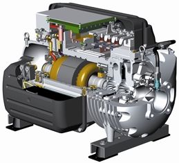
(A centrifugal compressor)
The typical centrifugal compressor is either a single stage machine with overhung rotor or a machine with multiple stages with a beam style rotor. A stage consists of the inlet system (for the first stage) or a return channel (for subsequent stages), the impeller, the diffuser (either vaneless or with vanes), and after the last stage a discharge collector or (in more modern machines) a discharge volute.
The gas enters the inlet nozzle of the compressor and is guided (often with the help of guide vanes) to the inlet of the first impeller. An impeller consists of a number of rotating vanes that impart mechanical energy to the gas. The gas will leave the impeller with an increased velocity and increased static pressure. In the diffuser, part of the velocity is converted into static pressure.
Diffusers can be vaneless or contain a number of vanes. If the compressor has more than one impeller, the gas will be again brought in front of the next impeller through the return channel and the return vanes. After the diffuser of the last impeller in a compressor, the gas enters the discharge system. The discharge system can either make use of a volute, which can further convert velocity into static pressure, or a simple cavity that collects the gas before it exits the compressor through the discharge nozzle.
The rotating part of the compressor consists of all the impellers and the shaft. This rotor runs on two radial bearings (on all modern compressors, these are hydrodynamic tilt pad bearings), while the axial thrust generated by the impellers is balanced by a balance piston, and the resulting force is balanced by a hydrodynamic tilt pad thrust bearing. The compressor shaft can be either a solid shaft, with the impellers shrunk or keyed on, or in modular rotors, the impellers can form part of the shaft.
The stability of the rotordynamic behavior of a compressor, that is, to operate without excessive vibrations within the desired range of speeds and pressures, is not only the key requirement for successful operation, but it also often limits the application of a compressor for certain applications (Nicholas and Kocur, 2005; Kocur, et al., 2007; Baldassare and Fulton, 2007).
Particular importance relates to the capability to sufficiently dampen the various possible excitations the rotor system may be subject to, be it from seals, impellers, unbalance, and others. To keep the gas from escaping at the shaft ends, dry gas seals are used on both shaft ends, except for overhung impellers, which only require one seal. Other seal types have been used in the past, but virtually all modern centrifugal compressors use dry gas seals, except for applications in air or nitrogen compression, where often carbon ring seals or labyrinth seals are used.
For dry gas seals, the sealing is accomplished by a stationary and a rotating disk, with a very small gap (about 5µm) between them. At standstill, springs press the movable seal disk onto the stationary disk. Once the compressor shaft starts to rotate, the groove pattern on one of the disks causes a separating force, making the seals run without mechanical contact of sealing surfaces.
The pressure containing casing is either horizontally or vertically split (Figure 5). The casing, as well as the compressor flanges have to be rated for the maximum discharge pressure the compressor will experience. Horizontally split casings are typically used for lower pressure applications (up to about 40 bar [600 psi] discharge pressure), while vertically split (barrel type) casings have successfully been used for discharge pressures up to 800 bar (12,000 psi).
The maximum amount of impellers in a casing is usually limited by rotordynamic considerations. Therefore, the maximum amount of head to be generated in one casing is limited. If more head is required, multiple casings, driven either by the same driver, or by separate drivers, have to be used. Another limitation for head may be the temperature limits of the compressor (typically, the discharge temperatures are limited to about 175 C/350 F). If more head is required, the gas has to be cooled during the compression process.
Various design alternatives are available:
- Multibody tandems, that is up to three compressor casings driven by the same driver, possibly with a gearbox either between the driver and the compressor train, or between two of the compressors.
- Compound compressors: This compressor contains multiple compartments, each with its own suction and discharge nozzle. All impellers are on the same shaft and face in the same direction.
- Back-to-back compressors: This compressor contains two compartments, each with its own suction and discharge nozzle. The impellers are on the same shaft, but the impellers in the first compartment face in the opposite direction from the impellers in the second compartment.
- Integral gear type compressors: Overhung impellers are located at each end of multiple pinions, driven from a central bull gear.
Either of these configurations does not only allow intercooling, but also sidestreams or gas off-takes.
(Peter C. Rasmussen is Chief Machinery Engineer, Exxon Mobil Corporation, Houston, Texas. He currently leads machinery research efforts at the ExxonMobil Upstream Research Company. He is a registered Professional Engineer in the State of Texas, and is a member of the Turbomachinery Symposium Advisory Committee.)
(Rainer Kurz is Manager of Systems Analysis and Field Testing, Solar Turbines Incorporated, San Diego, California. He has authored more than 70 publications in the field of turbomachinery. He was elected as an ASME Fellow in 2003 and is a member of the Turbomachinery Symposium Advisory Committee.)