Features of the oil-flooded screw compressor
In a dry-running rotary-screw compressor, timing gears ensure that the male and female rotors maintain alignment. In an oil-flooded rotary-screw compressor, lubricating oil bridges the space between the rotors, providing a hydraulic seal and transferring mechanical energy between the driving and driven rotor. Below are some features of the oil-flooded screw compressor.
This article contains excerpts from the paper, "Process gas applications where API 619 screw compressors replaced reciprocating and centrifugal compressors" presented by Takao Ohama, Yoshinori Kurioka, Hironao Tanaka and Takao Koga of Kobelco EDTI Compressors at the 35th Turbomachinery Symposium.
Power consumption savings by a built-in slide valve—The slide valve as unloader adjusts the inlet volume of the compressor, and this equates as power savings. Figure 4 shows the basic principle of the slide valve mechanism. The slide valve is located just beneath the rotors and moved in the axial direction.

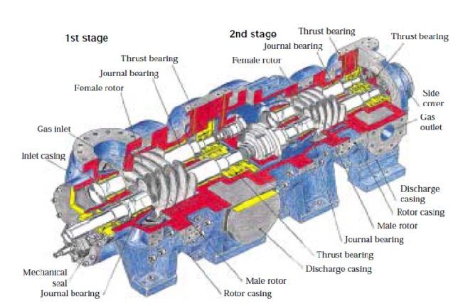
Construction of a tandem type compressor[/caption]
The slide valve is moved typically by hydraulic cylinder with oil utilized from the compressor lube oil line. Moving the slide valve to the suction side attains full load, and unloading is achieved by moving the slide valve toward the discharge port. At full load position, the entire length of the rotor is utilized to draw the gas so that inlet volume of the compressor can be maximized. By moving the slide valve to the unloaded position (i.e., discharge side), the length of the compression chamber is shortened. As a result, inlet volume of the compressor is reduced. Compression is done with less inlet volume of the compressor so that theoretical brake horsepower is reduced.
Low maintenance cost—Due to the lube oil system the rotors and many other parts of the compressor have an oil film on their surface. The life of the rotors is long enough so that a spare set is not required. The mechanical seal is typically one per casing, so maintenance and replacement cost for the seal are typically reduced.
Single skid arrangement— The compressor and lube oil system are integrated and packaged on a single skid. Thus, transportation and installation are completed in a short period.
No cooling water jacket/no gas bypass cooler—Since oil acts as coolant in the compression process, discharge temperature can be controlled by the oil injection flow rate so that the casing structure is made simpler by elimination of a cooling water jacket. The gas bypass cooler can also be eliminated by oil cooling.
Selection of oil is driven by the need to be compatible with process gas— Not only mineral-based oil, but synthetic oil has recently been used to expand the application range of oil-flooded screw compressors. Hydrotreated mineral-based oil has typically been used, but recently many are changing to synthetic oil. There are two kinds of synthetic oil: one is polyalphaolefin (PAO), and the other is polyalkylene glycol (PAG). With PAG there are several kinds of oil that differ in ratio of propylene oxide (PO) and ethylene oxide (EO). For a process with a heavy hydrocarbon, both mineral-based oil and PAO are subject to dilution; however, less dilution can be expected with PAG. There is no difference for dilution ratio by process with heavy hydrocarbon between mineral based oil and PAO; however, less dilution can be expected for PAG.