Solving subsea compression with technological innovation
DEEP OCEAN COMPRESSORS COULD OPEN THE DOOR TO VAST OIL AND GAS FACTORIES AND MARK THE BEGINNING OF THE END OF TOPSIDE RIGS
Sending a manned mission to Mars would represent an engineering feat for the ages. But not far behind in terms of technological innovation is the subject of subsea compression. As the quest for raw materials drives oil and gas companies farther offshore into deeper and deeper waters, at some point it becomes nearly impossible to push hydrocarbons to the surface with the existing degree of natural pressure.
“Some hydrocarbons become non-recoverable due to the loss of pressure during production,” said Rick McLin, Development Manager for Turbomachinery Control at Rockwell Automation, a company involved in subsea control systems.
Moving production to the seabed lowers the amount of pressure that is required to extract raw materials. McLin estimates that the use of subsea innovation could allow oil and gas companies to recover almost 20 percent more from producing fields. Additionally, capital expenditure could decrease between 30 to 40 percent, and overall operating costs could drop by nearly 50 percent due to decreased topside staff and supplies.
As subsea facilities feed directly to onshore production facilities, the need for fewer personnel and elimination of topside structures also reduces risk. Further, exploration can be expanded into smaller, deeper fields and into harsher environments, helping companies access the resources needed to meet worldwide demand.
The technological challenges are indeed staggering. But many companies are moving ahead with innovative projects that will soon make subsea a reality. Statoil, for example, recently used an underwater welding robot to install a tie-in point on a live gas pipeline at the Åsgard field in the North Sea at a depth of 265 meters without the pipeline being prepared in advance.
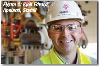
Figure 1: Kjell Edvard Apeland, Statoll[/caption]
"For a subsea engineer, this can be compared with landing on Mars," says Kjell Edvard Apeland, project manager of the remote-controlled development in Statoil and head of the operation on the Åsgard field (Figure 1). "When the compressor module and the manifold for Åsgard subsea compression are installed, we will connect the pipeline from these to the tie-in point.” Instead of taking three months to shut down the pipeline (at high cost) to execute the weld, Statoil managed it in 10 days.
Statoil is one of several companies involved in a race to be the first to land a centrifugal compressor on the ocean floor as part of oil & gas operations. Others in the race include Dresser-Rand, GE Oil & Gas, Man Diesel & Turbo, FMC Technologies, Sulzer Pumps, Cameron and Schlumberger.
It is all about exploiting ever deeper and more inaccessible oil and gas resources. Traditionally, natural gas resources use topside compressors which are expensive — the cost of a rig, its construction and deployment, daily operation, processing, ongoing maintenance, human safety and the environmental impact cost.
Subsea alternatives are a way to provide separation and compression capabilities to bypass the topside rig and deliver natural gas to onshore processing facilities via underwater pipelines. But to achieve that, the unit must be capable of continuous, trouble-free operation for many years.
“The biggest challenge is that a subsea compressor has to be maintenance free in a harsh environment,” said Klaus Brun, Program Director, Southwest Research Institute. “The casing needs to provide perfect sealing in a high-pressure, corrosive salt water environment and the process and cooling gas may contain contaminants and liquids that the compressor must be capable of handling.”
Technological challenges
Subsea compression requires three principal technologies: high-speed, direct-drive motors; magnetic bearings (with catcher bearings); and process gas recycling for motor cooling. These technologies have been commercial for several years, said Brun, but they are still not fault free. Any maintenance issue or failure of the compression system would require expensive lifting of the compressor to the surface, and in most cases these costs would be prohibitive. The compressor would just be abandoned on the bottom of the ocean.
“The only feasible compressor technology for subsea at this time is a direct-coupled, multi-stage centrifugal compressor that is hermetically sealed and driven by a high-speed electric motor using magnetic bearings,” said Amin Almasi, a turbomachinery consultant based in Australia. “There should not be a gear unit, lubrication or oil seal system, or dry gas seal system.”
Technological barriers have to be overcome, Almasi explained. On a subsea compressor, the compressed gas (often the gas after the first impeller) can be used for cooling the bearings and the driver. However, untreated or dirty gases for this job could cause problems. External cooling is one way to avoid dirty gas issues. But newer designs are finding ways to get around this challenge.
Magnetic bearings are being used to eliminate oil systems, but the relatively low-load limits of magnetic bearings pose an engineering problem. Roughly speaking, the load limit of magnetic bearings is around 50 percent of that of conventional oil-lubricated bearings.
Subsea factory
With so much gas trapped in subsea reservoirs, many at great depths, pressure is a big issue. As gas is extracted from the reservoir, the pressure drops. It gets to the point where it is difficult to pump gas up. A compressor on a surface platform can help. But it takes less power and is far more efficient to place one on the ocean floor.
Some are looking way beyond placing a few pumps and compressors at great depth. Norwegian oil and gas firm Statoil has unveiled more ambitious plans.
“We plan to have our first subsea factory on the seabed by 2020,” said Lars Christian Bacher, Executive Vice President of Development & Production International for Statoil. “It will contain all elements that are on a platform today.”
Early steps include the implementation of a subsea compressor at the Åsgard field by 2015. But before that, the company is following an extensive development period with a long series of final testing.
“The concept is being verified step-bystep, and Åsgard Subsea Compression in 2015 will be the next major milestone in verifying the technology,” said Statoil spokesperson Lars Gunnar Dahle. “Separation facilities on the seabed will be a key to success in Arctic areas or deepwater areas like the Gulf of Mexico and Brazil.”
Statoil is in the forefront of this technology; it is said to be the first to solve the problem of water and gas separation and injection, and first to develop a subsea facility for injection of raw seawater. Once subsea compression is fully realized, the whole subsea factory idea begins to look a lot more realistic.
“Subsea processing, and gas compression in particular, is an important technology advance to develop fields in deep waters and harsh environments,” said Dahle. The company expects the placing of compressors on the seabed to increase recovery by around 280 million barrels of oil equivalent.
Statoil has determined that towards the end of 2015, the pressure in the Åsgard reservoirs will become too low to avoid unstable flow and maintain a high production profile. Compression is necessary to ensure a high gas flow and recovery rate.
Figure 2: The North Sea is the proving ground for a subsea compression
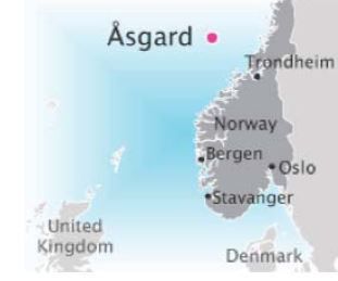
A large structure with compressors, pumps, scrubbers and coolers will be placed on the seabed close to the wellheads. A dry gas compressor system, for example, will be used on Åsgard (Figure 2). Gas and liquids are separated before boosting. The liquid is then boosted by a pump and the gas by a centrifugal compressor. After boosting, the gas and liquids are mixed into the same pipeline before transport.
“The closer the compression is to the well, the higher the efficiency and production rates become,” said Dahle. “By carrying out compression on the seabed, we also achieve benefits in the form of improved energy efficiency.”
Statoil has been testing subsea compression technology at its Kårstø laboratory since 2008. A full-scale model is now being tested under water, simulating actual subsea conditions. Two 10 MW centrifugal compressors as well as a scrubber, pump and cooler will be part of the initial installation.
But Statoil cannot establish subsea factories without the help of turbomachinery vendors. MAN Diesel & Turbo, for example, has been heavily involved in the Åsgard Subsea Project.
“Most of the new finds are in deep water and we need new technologies to be able to exploit them,” said Dirk Bueche, MAN Diesel & Turbo. “The goal of subsea compression is to increase our recovery rate, require fewer people offshore, minimize costs and boost reliability.”
MAN Diesel & Turbo’s High-Speed, Oil-Free, Integrated Motor (HOFIM) compressor has been on the market for several years now. It uses a high-speed motor and active magnetic bearings in a hermetically sealed design to eliminate dry gas seals and the complete oil system to reduce complexity, improve reliability and shrink the footprint (the size and weight are reduced by 60% and 30%, respectively, compared with traditional compressor designs).
MAN has already deployed a HOFIM compressor on a platform above the Ivar Aasen in the North Sea, run by Det norske oljeselskap. This unit is similar to the company’s subsea compressor, using a highspeed motor, active magnetic bearings, and a multi-stage radial compressor arranged in tandem configuration around a centrally positioned 9.5 W high-speed electrical motor.
“As well as the dry gas seals and oil system, the HOFIM design means you can remove the gears and use a high-speed motor to make a more compact, dense and flexible compressor,” said Bueche.
Subsea systems should be designed for simplicity and robustness as they have to deal with the high external pressure of the water. While the sea environment provides cooling for the compressor, materials have to be chosen carefully to avoid corrosion. Further, the compressor has to be remotely operable and have tolerance for wet gas.
For subsea operations, MAN has opted for a high-speed induction motor, a solid rotor, a variable speed drive and a barrel-type radial compressor with seven stages. The presence of these stages makes it possible to reduce compressor speed.
This machine can provide up to 11.5 MW with a maximum speed of 7,200 rpm, a maximum torque of 17.2 kNm, a voltage of 7 kV, a weight of 58 m.t., a pressure ratio of 2.8 and a flow value of 10,000 m3/h. MAN provides either a one- or two-barrel compressor per motor.
“Cooling of the motor and bearings is achieved via direct use of process gas. Symmetrical cooling of the motor from both sides minimizes thrust,” said Bueche.
The cooling gas system is comprised of the piping, one valve and one scrubber. Gas is extracted from an intermediate compressor stage and returned into the compressor suction. Bueche said that this generates a small amount of heating of the gas in the compressor suction, but this tradeoff is worth it, he said, as it makes the machine less complex. MAN has delivered three HOFIM products to customers to date.
Dresser-Rand (D-R) is working with Statoil, readying its Datum Integrated Compression System (ICS) for seabed deployment. The project focused on configuring the ICS package for highpower applications in a nominal 8 to 12 MW range.
The ICS platform uses high-efficiency Datum centrifugal compressor technology driven by a high-speed, closecoupled motor. The compressor rotor incorporates an integrated gas-liquid separation unit avoiding the use of a large static inlet scrubber to protect the compressor. The compression system has process gas coolers, process piping, valves, and instrumentation packaged into a single lift module.
D-R believes its joint development program with Statoil will help accelerate the market acceptance of the technology for both topside and subsea applications. Over the course of this year, D-R will be testing the marinized Datum I train in its liquid-gas hydrocarbon facility in Olean, N.Y., USA. In addition, the company plans to conduct testing on a subsea test stand alongside the existing facility, also in Olean. The Datum ICS can be deployed subsea to a location very close to the wellhead in order to enhance the production and field recovery ratios.
The ICS is a hermetically sealed, motor-driven/compression train, composed of the centrifugal compressor with an integrated centrifugal gas/liquid separator, and the high-speed, close-coupled, gas-cooled electric motor driver, with both rotors supported on active magnetic bearings (AMBs) manufactured by D-R’s Synchrony Business Unit, with a dedicated AMB control system.
"The motor and compressor casings form a hermetically-sealed, pressure containing boundary, so this type of solution does not require the use of dry gas seals at the compressor shaft ends,” said José L. Gilarranz, Manager for Technology Development and Commercialization for the ICS product line, at Dresser-Rand.
The purpose of using the integrated, gas/liquid separator inside the compressor body is to eliminate (or minimize the size of) the upstream, liquid handling, gravity-based scrubber vessel that is typically needed as part of a subsea processing module. These large diameter scrubber vessels are heavy, and for deep-sea applications the external pressure can be the most critical design constraint, adding weight and special handling.
When the liquid loading is low, it can eliminate the vessel altogether because of the integration of the gas and liquid scrubbing function within the Datum I compressor. For applications with larger liquid loading the vessel size can be reduced (especially the diameter) to make it more manageable, because it only has to handle easily separable coarse liquids (the final scrubbing is done in the compressor).
“Testing has shown that a centrifugal compressor can handle wet gas; however, the added liquid will increase overall power consumption,”” said Gilarranz. When you compare the power consumption required to boost a gas-dominant, multi-phase stream (Gas Volume Fraction > 95%) with a relatively high liquid mass content in a multi-stage centrifugal compressor (against the alternate solution based upon the separation and boosting of the liquid and gas as different streams) the former (direct wet gas compression) requires more power.
With high-head compression applications, it is possible to experience phase changes in the liquid being handled by the compressor. This can lead to a mismatch between the stages that compose the compressor flow path and may compound the power consumption problem. Also, the reliability of the overall system can be increased with a second line of defense inside the compressor that can protect the flow path components against the erosive effects associated with continuous liquid ingestion.
Features to reduce maintenance include the use of a closed-loop cooling system that circulates clean gas through the motor, the AMBs and a specially designed heat exchanger.
"Despite the fact that we are using robust, liquid-tolerant electrical insulation systems in the motor stator and in the AMBs, it is always a good practice to keep the electrical components away from liquids and other contaminants that could enter the motor bearing cooling system,” said Gilarranz.
These contaminants could cause premature fouling and result in hot spots that can lead to insulation degradation and subsequent damage.
"The main breakthrough will be to have several subsea units installed and performing, which will allow better end user acceptance of this type of technology,” said Gilarranz. ”Design adjustments may be required depending upon further testing and experience gained from installed units.”
Blue-C
Figure 3: GE Blue C subsea compressor
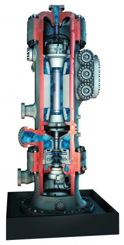
The GE Oil & Gas Blue-C compressor is in the finalizing phase of qualification testing (Figure 3). It is intended for unattended operation at almost 3,000 feet below sea level with power of up to 12.5 MW. Installation on the seabed is expected in 2019.
Blue-C is the first subsea product in the GE Integrated Compressor Line (ICL). A single-sealed housing can withstand extreme pressures and temperatures, and a simplified mechanical configuration has been developed for unattended operation.
The vertically stacked orientation of Blue-C protects the electric motor from raw process gas and drains liquids from the unit. This oil-free configuration also reduces the module’s overall footprint. The rotordynamic design includes three active magnetic bearings of the canned type. It is driven by a gas-filled, high-speed electric motor. A difuser separation system and dust removal device assists in wet gas compression.
Blue-C integration and submerged testing has consisted of 3,106 hours of operation, an inlet pressure of about 85 BarA and a discharge pressure of 145 BarA. Wet gas compression validation procedures are ongoing.
Cameron’s joint venture with Schlumberger known as OneSubsea has developed a subsea multiphase wet gas compressor. It is a counter-rotating multiphase compressor for boosting the pressure of an unprocessed wellstream. The three main parts are the upper electric motor, compressor section, and lower electric motor.
A barrier fluid system is used to provide overpressure protection, lubrication and cooling. This compact integrated unit has no need for an auxiliary anti-surge control system, inter-cooler or inlet scrubber.
This multiphase compressor is said to be able to tolerate 100% liquid without mechanical disintegration (i.e., slugs, a small volume of higher-density fluid, will be damped and transported through the compressor without interrupting operation). The unit also includes an upstream flow conditioner that suppresses slugs and provides a homogenous feed to the compressor.
Subsea pumping is another area where compressors are finding increasing deployment. “Subsea pumping is all about high boost as it allows more oil and gas to be produced,” said Rob Perry, Director of Global Subsea Processing at FMC Technologies.
Figure 4: A higher gas void fraction is achieved for a FMC/Sulzer multiphase pump driven by a permanent magnet motor
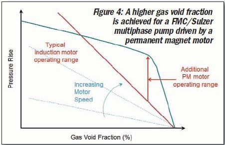
FMC Technologies has developed a permanent magnet motor that allows for high-speed pump operation relative to induction motors allowing for high boost at high gas void fractions (GVF) (Figure 4). It is coupled with hydraulics and a balance piston design from partner Sulzer that mitigate the thrust loads that are required to be taken by the thrust bearings. Using this approach, higher boost pressures can be achieved than previously possible, which translates into higher production for operators.
“FMC Technologies and Sulzer have developed a 3.2MW helico-axial pump and motor for subsea,” said Perry. “Smaller wet gas compressors using film bearings are also evolving.”
Sulzer and FMC are focused on larger format subsea multiphase pumps for ultralong step outs such as the Arctic, as well as high pressure, high temperature (HPHT) pumps for application in areas such as the Gulf of Mexico, where fields are characterized by ultra-deepwater and deep reservoirs (Figure 5).
Figure 5: This deepwater compressor from FMC Technologies and Sulzer Pumps is undergoing testing
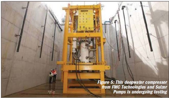
They are currently collaborating on a 6 MW 15,000 rpm, 350°F HPHT pump system with the aim of providing operators with flexible, reliable, and high performing solutions for projects that otherwise might not be considered economically viable.
“A more widespread adoption of subsea processing should occur as people stop artificially discounting subsea processing with higher risk factors,” said Perry. “A good example is Pazflor, which has maintained 99.5% availability.”
Subsea pumping
The Total Pazflor project in Angola has been producing oil and gas since 2011 using gas and liquid subsea separation and pumping systems supplied by FMC Technologies. Located 93 miles offshore, Pazflor’s resources are in water depths of 2,000 to 4,000 feet.
Three of the four Pazflor reservoirs contain heavy, viscous oil and relatively low reservoir pressures. Subsea gas and liquid separation and pumping makes production of this heavy oil possible.
Siemens, meanwhile, supplies power systems that operate subsea equipment. Siemens researchers in Trondheim, Norway have been working on how power network components behave when subjected to extreme water pressures.
“The goal is to develop a deep sea power grid that will supply energy to large oil and natural gas production sites at a depth of 3,000 meters,” said Bjoern Rasch, Head of Subsea Power, Siemens Oil & Gas Solutions.
This team is placing components sealed in oil-filled vessels under enormous pressure for months at a time to see if any cracks or deformations occur. Siemens Is also working on direct electrical heating (DEH) power supply systems for ten subsea flow lines for the BP-operated Shah Deniz gas field in the Azerbaijan sector of the Caspian Sea. Delivery of the equipment is scheduled for end of 2015.
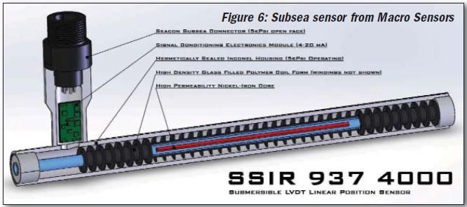
Sensors, too, pose problems for subsea compressor operators, particularly on the bellows designed to compensate for volume expansion due to temperature changes. Macro Sensors has introduced hermetically sealed LVDT linear position sensors to help deal with this problem. The sensors are directly submerged into seawater and mounted onto bellows to measure their position, said Karmjit Sidhu, Vice President of Business Development, Macro Sensors (www.macrosensors.com; positionsensors@ macrosensors.com).
“The LVDT provides position feedback to a surface-based monitoring control system for the compressors,” said Sidhu. “LVDTs are more reliable than other position feedback devices in these applications as these sensors can perform in depths up to 15,000 feet with high accuracy.” Macro Sensors has designed its SSIR 937 Series Submersible LVDT Position Transmitter to withstand deep sea environments with external pressures up to 7,500 psi. Inconel construction enhances the assembly to meet a 20-year lifespan even if exposed to seawater at depths up to 15,000 feet (Figure 6).
Figure 6: Subsea sensor from Macro Sensors
Final furlong
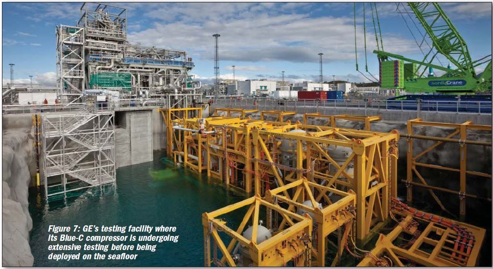
Very little of this technology has yet to make it to the seabed because the perceived cost of failure is too great. So further underwater testing will continue until the technology is proven (Figure 7). And even then, it will be deployed slowly over several years until it can be trusted on mission-critical resources.
“There have been significant technology advances on both the subsea compression and pumping side,” said Brun. “However, whereas subsea pumping has been deployed and is rapidly becoming proven technology, subsea compression is still undergoing testing and has not been commercially demonstrated. Unless there is a major failure, it is widely expected that in 2015 the Statoil Åsgard field will see the first operation of a subsea compressor.”
Figure 7: GE's testing facility where its Blue-C compressor is undergoing extensive testing before being deployed on the seafloor
