Validating the thermodynamic performance of a compressor
The main objective of the performance test as per ASME PTC10 or ISO 5389 is to assure thermodynamic performance of compressor as stipulated in contract data sheet.

Thermodynamic performance refers to gas horse power, polytrophic head and flow and the shape of the head-versus-capacity characteristic curve. It should be well noted that during test, only 1
st
stage suction impeller’s aerodynamic performance is actually validated.
Option on type of tests
There are three classes of ASME loop tests out of which class II is mostly used with relatively higher density test gas, in accordance to test codes with lower speed and lower power.
Class III Tests
This test is the same as Class II except that compressibility factors are applied along with changes in “k” value from suction to discharge.
If the main objective of such a test is to determine mechanical behaviour at high-pressure levels along with aerodynamic performance then a closed loop Class I test should be conducted.
If there are more than two numbers of similar types of compressors, three pragmatic options can be exercised by end user:
1. PTC 10 type 1 / type III for one compressor with mechanical run test and mechanical run test for second compressor
2. PTC 10 type 2 test for both compressors
3. Only one PTC 10 type 2 test based on manufacturer’s assurance on dimensions of gas path of compressor.
A full-load, full-pressure, full-speed (FLFPFS) test is often called for when the
compressor train is in gas injection service or other un-spared services where the discharge pressure exceeds the 200 bar. The appropriateness of the FLFPFS test is related to the density of the gas in the compressor casing. Highly dense gases can cause excitation of the rotor resulting in destructive levels of sub-synchronous vibration.
The frequency of the sub-synchronous vibration is usually higher than that of the first critical speed, but lower than the frequency of running speed. Verification of cross coupling forces damping by using an Electronic shaker at extended portion of Non Drive End can be executed. The overall damping of the compressor is determined by evaluating the rotor vibration response to a non-synchronous unbalance produced by the exciter.
Special set up and calculation software are required for Wet Gas Compressors.
It is imperative to optimize the extent of tests mentioned for each heading based on equipment criticality. Test engineer should be careful that same EOS is used in estimation and post-test calculation as different equations of state yield very different test results risking rejection of machine.
Detection of surge point at a particular speed during a performance test is based on criteria i.e. Flow and discharge pressure instability (deviation in read out by more 5 %). One should not advent to pull the compressor operating point when surge related audible noise is generated.
Post Test Calculation
While calculating polytrophic head, assurance of accuracy in estimating the correction factor is very important. If the concept of similitude is used manual calculation based on enthalpy balance and comparison with corrected and predicted performance becomes simple.
To exercise the rule of similitude, the volume reduction ratio (V1 /V2) for contractual condition and test bed condition must be equal. It is quite tricky to set speed with respect to volume ratio as thermodynamic behavior is not fully compliant to Fan laws.
The curve plotting shall be more accurate if the number of test points at the same normalized speed is a minimum five. To have a realistic and close predicted shape of H-Q curve, cubic fitting should be exercised in curve plotter. To calculate the slope of a curve, the derivative of the curve's function is to be calculated. There are several methods for calculating the derivative, but the power rule is the simplest method and can be used for most basic polynomial equations.
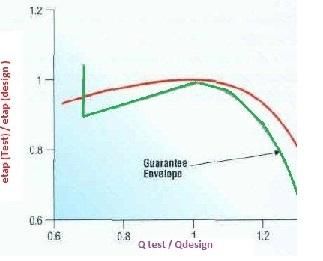
It is advised that predicted and tested compressor performance curve should be non-dimensional so that property of impeller aero-thermodynamic performance is easily validated, or test procedure shall show a guarantee window.

Reynolds number correction
The corrections suggested by test codes are often inclined to favor the vendor. The ICAAMC method of Reynolds number correction includes the friction factor concept that is used in the analysis of flow in piping. For better understanding, API RP 14E (Modified Moody Diagram) can be referred.
Reynolds Number correction is essentially an attempt to account for boundary level differences between the specified condition and the test condition. Typically performance testing to industry standards is conducted at lower Reynolds Number and therefore the flow, head and efficiency will measure lower in the shop test versus a test done at specified conditions. This penalizes the manufacture.
The current correction methods correct observed data relative to the inlet and discharge flange condition. In reality, the Reynolds Number effect is on each individual stage particularly later compression stages. Therefore, any Reynolds Number correction must include a term for volume reduction. Hence an OEM should test at a Reynolds Number where any correction is insignificant. The test procedure should follow a preamble - Minimum Reynolds Number at test must be 10% of specified, but not less than 1 million. Reynold’s correction is not allowed.
References
1. Compressor performance – Ted Gresh
2. Hydraulic shop performance test of Centrifugal compressor – Gary Colby turboproc/T34/t34-15