Case Study: Maintenance Tips for Magnetic Drive Pumps
Pumping molten sulfur can be challenging for end users. With several design options, knowledge of proper system maintenance is crucial.
At a Saudi Aramco facility, two magnetic drive pumps (Unit A and Unit B) were installed in a sulfur-treating unit to transfer liquid sulfur to a pestillator. Both ran 100% in continuous operation. These pumps were crucial, and failure would lead to a shutdown of the sulfur-treating unit. Due to continuous failure of the pumps, the plant elected to purchase an identical unit, as a spare, to improve system availability. At one point, two pumps were out of service, and the spare pump was installed onsite. However, the spare produced abnormal sounds. Fears of operational instability prompted an investigation.
A mechanically sealed pump can be used with a high amount of hydrogen sulfide (H2S) and total suspended solids (TSS). If TSS is high, a magnetic drive pump isn’t recommended. Hydrodynamically sealed pumps should be used when the process requires constant runtime, without frequent stoppage and positive suction pressure. Such design uses an auxiliary impeller to act as a dynamic seal.
The molten sulfur pumps are magnetic drive centrifugal pumps with the following design parameters (Table A-1):
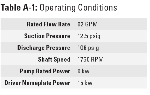
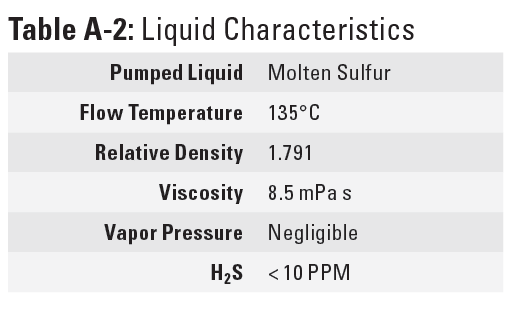
Table A-2 below summarizes the liquid characteristics.
Magnetic drive pumps contain heating areas in which the pumped liquid (sulfur) must be kept at a constant temperature to avoid solidification of sulfur and keep it in its liquid state.
FINDINGS
Several issues were discussed. Principally, the pump would not deliver sulfur at the required discharge pressure. The suction pressure was 14 psig and the discharge pressure was only 18.5 psig instead of the rated 106 psig. Further issues included:
- Magnetic coupling failing due to high temperatures inside the magnets.
- The system steam temperature was greater than 135°C, exceeding maximum tolerances.
- Evidence of magnetic coupling slippage and abnormal sounds eminated from the pump bearing housing.
- High casing vibration made the pump trips.
- Instrument gauges experienced frequent plugging.
- The pump vendor cited several possibilities, and the plant was instructed to check:
- The correct fill level in the suction tank to prevent air pockets in the suction area, determined by draining the sulfur from the pump casing.
- Inner magnet might be demagnetized, leading to a tumbling effect of the impeller. A demagnetization of the inner/outer rotor can occur if the pump is operated for a long time with a ruptured magnetic coupling.
Temporary suction line strainer, as it might be clogged. - Steam temperature inside the pump (steam line), as it might be too low due to high condensate content.
- Integrity of the discharge valve. If the pressure does not change when opening and closing the discharge valve, the valve might be clogged, or the non-return valve is not working properly.
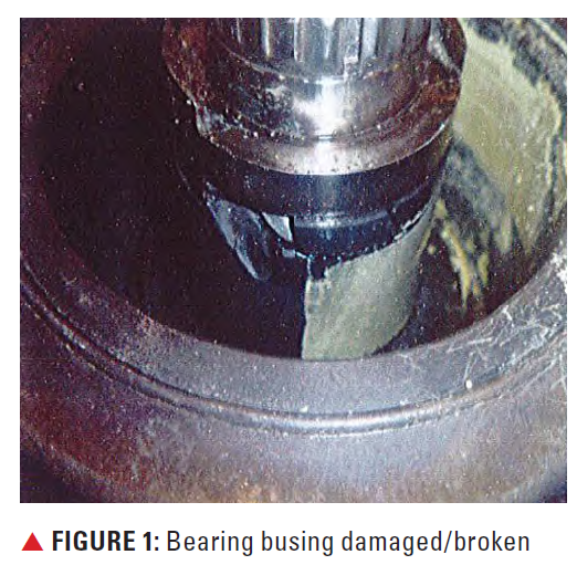
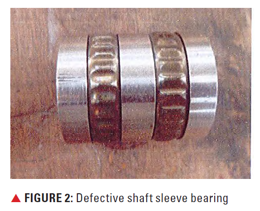
An extremely loud pump is an indication that the magnetic coupling is completely ruptured. After dismantling the pumps, several parts were shown to be damaged or broken. For Unit A, this included the bearing bushing (FIGURE 1), casing gasket, small pieces of the magnetic coupling ring, and the shaft sleeve bearing (FIGURE 2). High run-out was observed on both the top and pump shafts.
The plant contacted central engineering to investigate further. The company’s internal standards mandate the magnet torque rating to exceed the maximum torque of the pump (with maximum diameter impeller) by at least 50%. Torque value was calculated at 81.85 Newtonmeter (N.m). In this case, the maximum pump power is 17 kW, which means the synchronous magnet torque rating cannot be less than 139 N.m. However, the company was advised to use 99 N.m for testing the used magnets.
To test the integrity of the magnetic coupling, a special tool was fabricated for the drive shaft. Essentially, an M16 welding screw with an M24 nut (FIGURE 3).
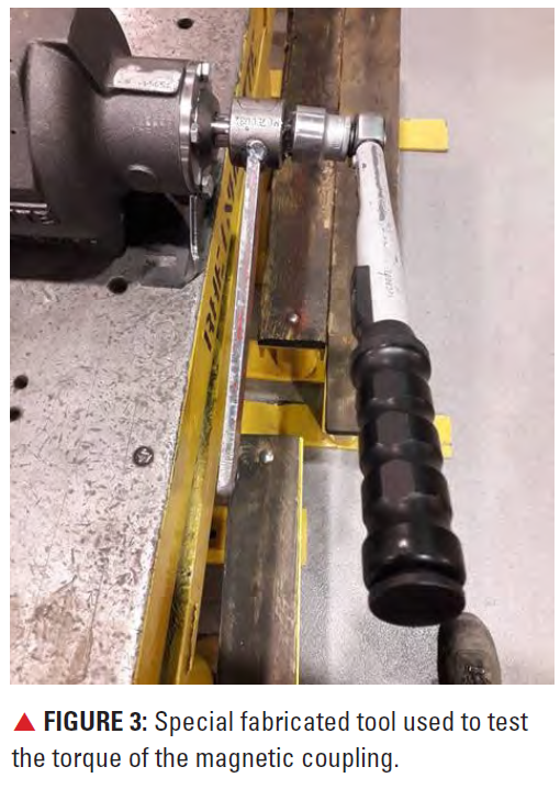
On the lathe machine, the inner magnet was fixed to the lathe head while supporting the outer magnet on two lathe machine bearing holders. The special tool was mounted on the drive shaft until it reached the end of the thread. A torque-wrench placed on top of the special tool welded nut allowed adjustment to 99 N.m. They were to turn the wrench until the magnetic coupling moved or the wrench clicked.
For Unit A, the magnetic coupling slipped when the torque reached 35 N.m., indicating the magnet lost 60% of its strength. For Unit B, the torque test reached 99 N.m without any slippage, a positive result.
PUMP CASING AND JACKETING TESTING
Several tests were performed to check the integrity of the casing and its drain, which should only be exposed to sulfur. But for this test, water was used in lieu of sulfur. Similarly, the casing and back cover jacketing should only be exposed to steam, but for this test, air was used in lieu of steam. The tests checked for pinholes between the steam and sulfur side.
The pump was pressurized between 20-80 psig with water. Air was injected in the inlet steam line. Water did not exit the steam drain line. Air did not mix with water; water was drained from the discharge line, and air was injected to test if steam would mix with sulfur. Air only came out of the drain point, and water through the discharge line. Water was injected into the steam line inlet. It only came out of the drain line. Another water and air test was conducted for the other half of the pump. Water was injected into the pump suction, exiting through the discharge point.
This confirmed that the existing steam jacketing had no pinholes, so sulfur could not enter the outer magnet jacket. For this pump, steam enters the front casing at the top and leaves from the bottom to go to the top of the outer magnet jacket. It then exits from the bottom of the outer magnet steam jacket connection.
RECOMMENDATIONS
Central engineering recommended that a new magnet set be ordered for Unit A. The plant will conduct the test again after receiving all the materials, including bearings. The temporary suction strainer should be removed, and a check should be made on the suction gauge.
Before any pumps can be started, the shaft must be turned by hand. The
high-amp trip set point should be around 13.2 AMP. The end user should add calibrated pressure transmitters, if possible, and conduct the pump performance test. After removing the temporary suction strainer, the plant found the low discharge pressure issue disappeared. This strainer should only be used while commissioning the pumps and might be used a few months after full start-up. It should never be used after ensuring the lines are clean. The suction strainer is the main reason behind the starvation of these pumps, leading to failures.
FUTURE PLANS & PROPOSALS
In this case, several fruitful observations and suggestions can be made. All instruments were out of service or not reading correctly, highlighting the importance of maintaining a supply of spares. Replacing one of the pumps with a hydrodynamically sealed pump would enable constant uptime. One magnetic pump should be kept for emergencies. However, that solution is costly because the hydrodynamic pump skid has completely different dimensions.
Wesam Khalaf Allah is a Rotating Equipment Engineer with 10 years of experience at Saudi Aramco, specializing in pumps and mechanical seals.
Amer Al-Dhafir is a Rotating Equipment Engineering consultant with over 20 years of experience in pumps and mechanical seals.
