High-pressure compressors and how to select the right test
BY JAMES SOROKES
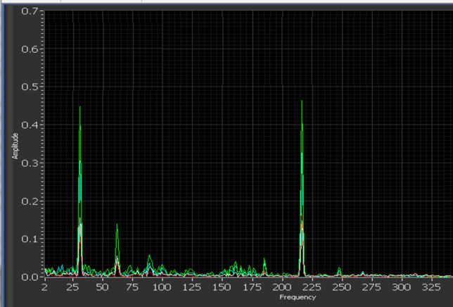
Onset of diffuser stall during a Type 1 test

An obvious objective is to confirm the compressor will perform as predicted. But an equally important goal is to minimize the risk of unexpected aero-mechanical issues during field installation, especially in remote locations such as offshore platforms. It is far better to uncover potential problems before the equipment leaves the original equipment manufacturer’s (OEM) facility.
High-pressure and high-power density compressors typically experience rotordynamic (instability) and aerodynamic (stall) complications more often than compressors intended for petrochemical service. Thus, the demand for more rigorous in-house testing has grown. In response, OEMs and the turbomachinery community developed a variety of test programs and facilities to demonstrate that equipment meets end-user requirements.
These options include:
• Volume reduction, inert gas tests using small open- or closed-loops (typically called Type 2 testing according to PTC 10, “Performance Test Code on Compressors and Exhausters,” ASME International, 1997)
• Full-load, full-pressure, full-power testing with the contract drivers, gears, auxiliaries, complex piping systems, and so on (typically labeled Type 1 testing)
• Each type of test offers insight into a compression system’s aerodynamic and mechanical behavior. Type 2 low-pressure inert gas performance tests are set up based on compressor volume reduction (i.e., exit volumetric flow divided by inlet volumetric flow).
A critical parameter in assessing multi-stage compressor performance is the combined volume reductions of the individual stages to determine the overall volume reduction of the compressor. Thus, the volume reduction of stage 1 determines the volumetric flow into stage 2, which sets the flow into stage 3, and so on.
Volume reduction tests use readily available gases, such as nitrogen, helium- nitrogen mixtures, carbon dioxide and R-134A refrigerants. The selection of test gas or gases, operating speed, and so forth are made to match as closely as possible the volume reduction the compressor will experience in the field.
Type 2 tests are also run at lower pressures than the compressor will experience in field operation. A Type 1 test, per the ASME code, is run with a gas mixture close to the gas compressed at or near operating conditions expected at the site. If it is possible to conduct the test using the actual field gas and field inlet conditions there may be no deviations between the field and test conditions; however, this is rare.
In most instances, the inlet temperature at the specified condition cannot be achieved due to an OEM’s test stand cooling capacity limits, and it is often impossible to exactly match the field gas. While a different gas can be used, it must have a k-value (a measure of thermal conductivity) close to the field gas to ensure test and field Mach numbers are equal and the thermodynamic conversion of the work input to the gas produces the same pressure ratio.
Generally, Type 1 test results accurately reflect field performance levels and end users should expect little or no difference between the performance measured during Type 1 testing and those in the real world. The Type 1 test exposes compressors and their auxiliaries to near field conditions. It offers a greater likelihood of uncovering abnormalities in performance (mechanical or aerodynamic) compared to Type 2 tests. Therefore, end users must weigh the higher cost of the Type 1 tests (as much as 10 times) against potential production loss that might arise.
Test selection
Numerous factors can impact the aerodynamic and mechanical behavior of turbomachinery and the selection process for Type 1 or Type 2 tests. These mostly relate directly or indirectly to the higher pressure and aerodynamic loading experienced on the Type 1 test. Primary among these are deflections or relative movement of parts. As a result, there can be subtle differences in the primary and secondary flow path geometries under Type 1 and Type 2 test conditions.
For example, one of the most common geometric changes that might occur during a Type 1 test (but not under Type 2 test conditions) is bundle deflection due to manufacturing tolerance stack-up. In a typical re-injection compressor, the highest pressure occurs in the last-stage diffusers (for both straight-through and back-to-back arrangements). Thus, forces on the sidewalls of the last-stage diffuser will cause the diffuser walls to move apart. As the last-stage diffuser is also typically the narrowest in a compressor, its behavior is more sensitive to axial deflections.
The amount of deflection depends on the machining tolerances of the bundle components and the fits, as well as material deflections that might occur from pressure forces or thermal effects. Typically, maximum deflections are in the tens of thousandths of inches (or tenths of millimeters) and of little consequence in most compressors.
However, if the design diffuser width is narrow (often the case with high-pressure reinjection compressors), tens of thousandths of inches can be a large percentage of the diffuser width. It is possible for the width to increase sufficiently for diffuser rotating stall to occur, resulting in high levels of subsynchronous radial vibrations. This probably would not be evident during a lower pressure Type 2 test. In one instance, had a Type 1 test not been run at the OEM facility, this exact problem would not have been discovered until the compressor came on-line in the field. The significant warranty implications to the OEM and lost revenue to the end user due to production disruptions would likely dwarf the cost of a Type 1 test. It is advisable, then, that end users, process engineers, and OEMs discuss compressor testing at the OEM’s facility to address aero-mechanical concerns prior to shipping equipment to the site. ■
James Sorokes, is Principal Engineer at Siemens Oil & Gas in Olean, NY. A paper on this topic, “A Comparison of Type 1 versus Type 2 Testing – Recent Experiences Testing A High Pressure, Re-Injection Centrifugal Compressor,” (Sorokes, Kocur, et al) was presented at the 2019 Texas A&M Turbomachinery & Pump Symposium. For more information, visit Siemens.com
