How PTC-10 Has Evolved
Improving compressor performance test accuracy
ASME Power Test Code (PTC)-10 establishes standards and rules for conducting tests that determine compressor thermodynamic performance at specified operating conditions. The primary goal of thermodynamic performance measurement is to estimate some kind of reference or ideal work input, actual shaft work input, and resulting thermodynamic efficiency. However, such estimation requires measurement of many other quantities. PTC-10 has attempted to provide standardized methods to measure relevant quantities and calculate the performance.
Since the first version of PTC-10 was published in 1935, it has been periodically reviewed and revised to provide updated testing standards as compressor applications have become more diverse. While the 1935 and 1949 versions provided initial guidance for compressor performance measurements, it was the 1965 version that started addressing real gas behavior in performance measurements. An examination of the versions starting from 1965 until now reveals how the code’s compressor performance measurement has evolved over time and may continue to evolve.
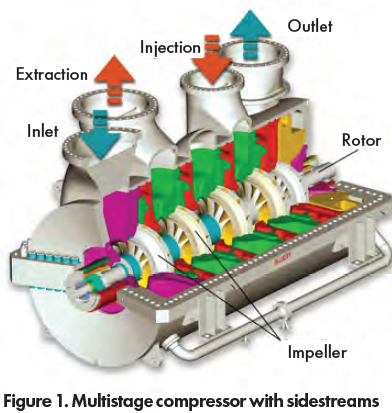
1965 – The previous two versions of the code depended mostly on ideal gas laws and generally assumed the test was conducted at the site installation. This revision attempted to address the growing field of compressor applications using non-ideal gases, and to make provisions for the use of multistage compressors with sidestream injection and extraction flows. It established manufacturing shop procedures for testing gases that differ greatly from the specified gas at the compressor installation site. Some of the concerns addressed included: permissible variations in gas properties between the substitute gas and the actual contract gas, the process to obtain reliable thermodynamic properties of the gases, and conversion of test performance values to the guarantee or specified values.

New terms added in the Definitions section include volume ratio, machine Mach number, and machine Reynolds number. The surge limit was added to the list of quantities to be determined by the performance test. Surge and methods to detect it during a test are also described. This code also introduced a new method for classifying tests based on the test gas and the thermodynamic properties at the design point test conditions.
Three test classes were defined. Which test class is conducted depends on whether it was performed at specified gas conditions, or on a substitute gas at different operating conditions. Class I tests are made with the specified gas at the contract speed, inlet pressure, and inlet temperature within the allowable departure (%) limits. Class I tests should be used wherever feasible. Class II and Class III tests are conducted at different operating conditions from the specified and/or other gases, depending on the amount of departure of the gas properties from perfect gas laws. The code defines limits that are referenced to both the specific heat ratio and the compressibility functions. The Class II tests lie within the specified limit values, while the Class III tests fall outside those limits. If these limits are exceeded by either the test or specified gas at any state point along the compression path, then the formulas designated in the code for “real gases” must be used to calculate the performance parameters.
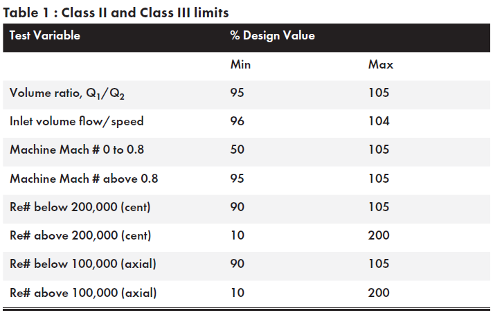
Both Class II and Class III must meet the limits in Table 1 at the design or guarantee operating point. Mechanical losses cannot exceed 10 percent of the total shaft power at the test conditions. This version of the ASME Power Test Code warns that those setting up the test conditions need to verify the accuracy of the gas properties they are using. If the properties are not reliably known, then the test does not comply with the code. Uncertainties in the overall calculations should be evaluated prior to the test to determine if the proposed test will meet the required accuracy. This is the first time the concept of uncertainty analysis was included in the test code. However, the code does not include a method to calculate the uncertainty.
The code also requires that compressors with liquid-cooled diaphragms be tested on the specified gas using Class I tests only. Descriptions of the various compressor test arrangements and their associated flow meters are included (like previous versions of the code), along with several drawings. For the first time, square-edged orifice plates are listed as acceptable flow meters. Reference is made to PTC 19.5 (4-1959) for obtaining their associated flow coefficients or K. Also, several types of flow straighteners are described.
This code revision adopts a new method for calculating polytropic work (head), developed for use with “real” (non-ideal) gases, and introduces the term, polytropic work factor in the head equation. Another new procedure was added for adjusting the tested performance to the specified as a function of the ratio of test to the specified machine Reynolds number.

The method was derived from one established for axial compressors, since at this time, there was little published test data on the Reynolds number effect for centrifugal compressors. Therefore, to be conservative, the efficiency correction was reduced to about half of the axial correction.
The polytropic head is also corrected by the same ratio of specified to test efficiency. It was not uncommon for compressor manufacturers to apply only half of the resultant efficiency correction to the test due to the magnitude of the full correction, and possibly because of some skepticism from the compressor purchaser. The 1965 code also provides examples of Class I, II, and III tests, with detailed calculations showing test values converted to specified conditions.
1997 – Up to 1965, the average time between code revisions was 15 years. Thirty-two years later, the 1997 revision was published and is 195 pages, more than twice the length of the 1965 version, including 100 pages of sample calculations. The code committee reaffirmed this version in 2009, and then again in 2014. In it, the basic list of parameters determined from the performance test has grown to include: quantity of gas delivered, pressure rise produced, head, shaft power required, efficiency, surge point, and choke point.
This edition of the ASME Power Test Code includes more detailed explanations of the procedures and their associated sample calculations. The main changes are: discussion of uncertainty analysis, a new performance correction method based on the Reynolds number, requirements for the treatment of sidestream flows, definition of the allowable departures of machine Mach number and Reynolds number from specified in the form of graphs, revision of the test class or type of test to two (Types 1 and 2), and requirements for multipoint tests.
The code committee wanted to demonstrate how measurement error could propagate to the final calculated results, and that such an analysis before the test can help in choosing instrumentation and methodology. The degree to which uncertainty analysis may be applied to any test depends on the specific test objectives. Based on this, the code makes no firm requirements regarding the use of this analysis and advises addressing this issue prior to the test. Although these calculations can be complex, the 1997 code considers that personal computers now allow for the associated equations and procedures to be programmed and solved rapidly. PTC 19.1 is referenced for providing step-by-step calculation procedures for performing an uncertainty analysis.
By the mid-1970s, both manufacturers and many end users of centrifugal compressor equipment acknowledged that the code correction to efficiency based on the Reynolds number was too large. As a result, the committee adopted a new method based mainly on Wiesner’s work with some simplification for ease of application. However, some end users prefer the ICAAMC method, and have asked that it be applied for their performance tests instead of the recommended one.
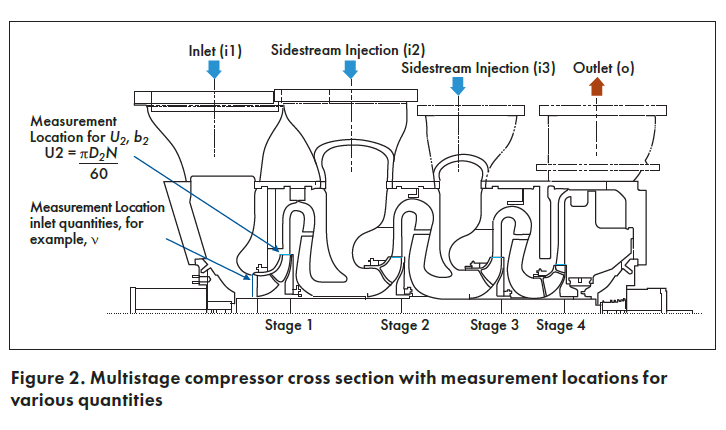
Because of the many petrochemical processes requiring multi-section compressors with injection or extraction side streams, the 1997 code tried to provide better guidance for test procedures under these circumstances. It gives clear specifications for the allowable range of variation of sidestream to upstream volume flow rate ratio. These limits are especially important for Type 1 tests at site where only conditions at the compressor flanges (internal data not available) are normally measured. Type 2 tests are commonly performed at the manufacturer’s facility where internal pressure and temperature instruments can be installed. The code only requires the temperature to be measured internally to allow calculation of both the upstream section head and efficiency, and the internal mixed temperature of the downstream section inlet. Internal pressure is not required to be measured and is allowed to be estimated based on the sidestream flange pressure. It also warns to be cognizant during the test of the flow stream temperature differences, which could cause thermal stratification.
For tests requiring multiple points from choke flow to surge flow, the same equivalency rules with respect to volume ratio, Mach number ratio, and Reynolds number ratio apply at each point. Also, the same sidestream to upstream volume flow ratio tolerances apply at off-design points, unless otherwise specified prior to testing. Multipoint tests are now quite common, and typically follow the recommendation of five points to define the necessary performance curves. Purchasers of variable speed compressors often will require additional test points at alternate speeds to define a surge line. Determining choke flow was a new addition, and an explanation is included on how to achieve it on test. However, depending on the compressor and test loop arrangement, a clear definition of choke flow may not be possible.

Thus, it is important that the purchaser define this requirement well in advance of a test. This allows the testing facility to investigate the best means to achieve choke flow or to define the highest flow possible based on the test loop system resistance.
CONCLUSION
PTC-10 has evolved with both changes in technology and with design and testing of various compressor configurations. It has been almost 25 years since the last version of the code. The limitations of the current version, including its accuracy in evaluating centrifugal compressor thermodynamic performance have been discussed, and the need for an upgrade debated.
Many methods have been proposed for correction of performance prediction based on deviation of Reynolds number from nominal conditions. This includes a unified method for correction of the effects of the Reynolds number, size, and roughness. Such changes in both the performance calculation and correction method should lead to a more accurate compressor performance result and are expected to find a place in future updates of the ASME PTC-10 code.
Kapil Panchal, Engineer V Compressor Aerodynamics, Elliott Group, a compressor manufacturer based in Jeanette, PA. For more information, visit www.Elliot-Turbo.com

William Hohlweg, retired, Elliott Group. For more details on the references and equations related to this article, please email info@elliott-turbo.com

