Recycle Gas Compressor Challenges
Dynamic simulation of compressor anti-surge system demands special care.
Recently, a series of tests were performed at a Saudi Aramco refinery continuous catalyst regeneration plant (CCR) to examine compressor trip mitigation. Two recycle gas compressors operating in parallel at 50% capacity feed H2 to the CCR. Each compressor is rated for 6 MW, with a maximum continuous speed of 6,200 rpm. They enable hydrogen-rich gas circulation in the reactor circuit. A steam turbine (K-400B) and a variable frequency drive (VFD) electric motor (K-400 A) act as drivers. Each compressor had a different head, so the start-up and shutdown sequences were complicated, and required special consideration. Steam turbine tripping necessitated a total plant shut-down since it could not be restarted while the motor driven compressor was running. K-400B trips lasting longer than four hours and led to total plant shutdown or 60% capacity operation.
BACKGROUND
Uncovering design limitations of the CCR compressors during commissioning indicated major operational issues for the CCR plant. The current engineer-procure-construct (EPC) design called for a start up of the steam turbine driven compressor (K-0400B) prior to start up of the motor driven compressor feeding H2 to the CCR. This wasn’t reflected in any of the process licensor or EPC documents.
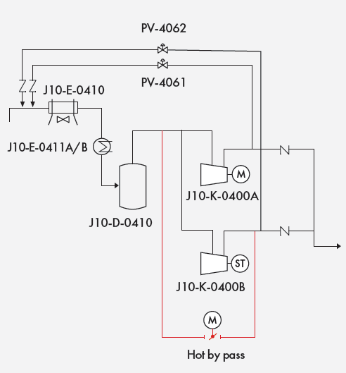
During normal unit capacity, K-400B can’t start while J10-K-400A is online, as K-400B can’t develop pressure at idle speed. Upstream pressure of the J-10-E-410 (reactor effluent air cooler) would be almost 2.8 barg while K-400A is running, and lead to K-400B going into surge with the existing piping layout (Figure 1).
Figure 1: Schematic of H2 recycle gas compressors. Courtesy of Saudi Aramco.
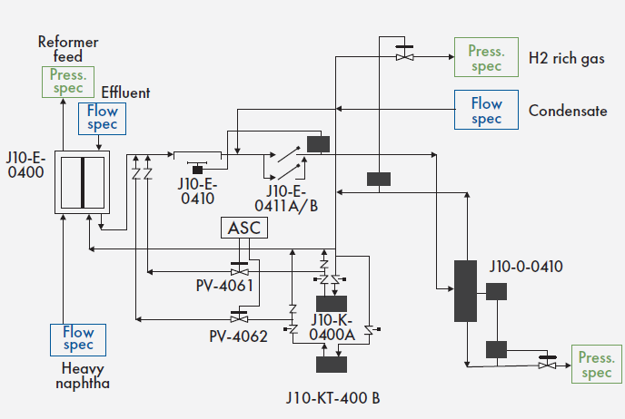
Idling mode with 1,500 rpm is required for the compressor turbine KT-0400B prior to increasing the turbine speed to its minimum 4,200 rpm. It cannot be carried out when K-0400A is in operation, since a compressor head with 1,500 rpm is not sufficient to overcome the required discharge pressure developed by the reactor effluent and recycled gas flowing through the effluent condensers. The anti-surge spillback line is taken from the individual compressor discharge and connected upstream to reactor effluent condenser E-0410. With K-0400A running, pressure drop is created through E-0410, E- 0411A/B, and the associated piping. It was too high for K-0400B under idle, and thus, shall be lower than the achievable discharge pressure at 1,500 rpm.
For any Reformer Reactor Circuit, an H2 recycle gas compressor system pressure is governed by the naphtha liquid feed. Reactor circuit pressure drop and recycle gas pressure is largely determined by hydrocarbon flow, rather than compressor speed. This means while K-0400A is running, altering its speed will not influence the reactor circuit pressure drop as much as the liquid feed.
MITIGATION PLAN
By starting K-400 B first, idling operation can be performed before increasing turbine speed. After reaching minimum turbine speed on compressor-B, compressor-A starts. Afterwards, liquid hydrocarbon is introduced to the reactor. If compressor-B is tripped for any reason, several solutions can alleviate the issue of common tie-in of the compressor’s recycle line to the effluent condenser, mitigating operational limitations.
One route involves continuing turndown operation only with compressor-A, until problems with compressor-B can be resolved. Once compressor-B is fixed, idling operation of the compressor-B turbine can commence. Next, shut down the unit by stopping the feed; then shutdown compressor-A. With intermediate storage tanks, the upstream/downstream units can continue, so impact on the aromatic production should be limited. The upstream naphtha hydro-treating (NHT) will continue to run by sending hydrotreated naphtha to the hydrotreated naphtha storage tank.
Figure 2: New line to depressurize compressor-B to flare during idling. Courtesy of Saudi Aramco.
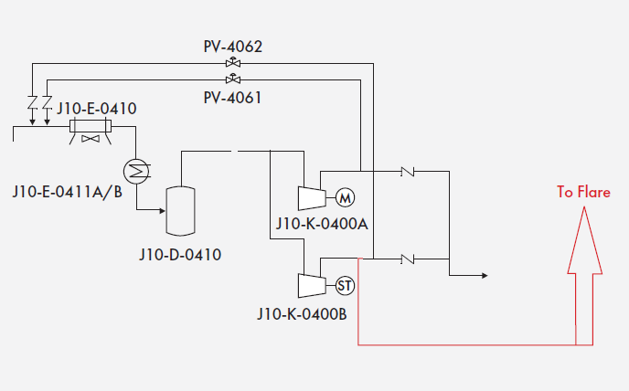
Another is to provide a new recycle line from the compressor discharge to flare so that the compressor-B’s discharge can be depressurized to atmosphere. Hydrogen rich gas would be vented and lost to flaring (Figure 2).
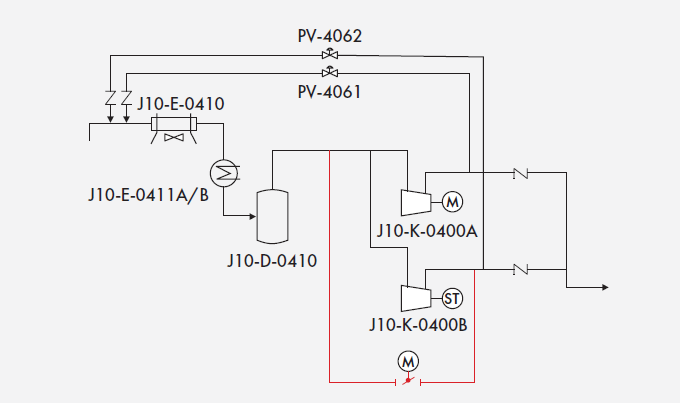
A third choice is installing a new recycle line from compressor-B’s discharge to the compressor common suction before the split to the compressors. This ensures compressor-B operates independently from compressor-A during idling, as both compressors have a dedicated loop (Figure 3).
Figure 3: Proposed piping modifications to enable idling. Courtesy of Saudi Aramco.
SOLUTION EVALUATION
Both the first and second options ended up being excluded. One leads to major process interruption and requires extensive effort to shut down and restart the plant. Number two extrudes high levels of hydrogen rich gas to the atmosphere.
Option three was deemed the best solution. It provided higher operational flexibility, is less harsh on the environment, and only requires minor piping modifications. To eliminate compressor-B surge during turbine idling operation, the discharge pressure of compressor-B must be depressurized and equalized to the suction pressure. This is achieved by providing a new line, bypassing the reactor effluent condensers. With low-speed idling, the temperature rise through compressor-B is marginal, and the required flow rate is small compared to the gas flow rate circulated with compressor-A. Idling operation can be done without temperature escalation at compressor-B’s discharge, as long as the discharge gas is combined with gas from the separator (compressor-A). Here, no additional spillback gas cooler is required (Figure 4).
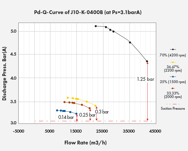
Figure 4: Compressor performance curve at different proposed idling speed.
Courtesy of Saudi Aramco.
COMPRESSOR EVALUATION
The differential pressure across J10‐E‐0410, J10‐E‐0411A/B and the associated piping is expected to be approximately 0.2-0.25 bar under 50 % operating load, as per a system hydraulics simulation. According to the performance curve provided by the compressor vendor, the allowable pressure differential between compressor suction and discharge in the idling mode (1,500 rpm) is limited to 0.14 ‐ 0.20 bar. Raising the idle speed was needed to meet differential pressure of 0.2 bar at 50% load. The compressor and steam turbine vendor proposed up to 2,200 rpm for idling compressor-B, which is near the critical speed of the train. This wasn’t possible, as the steam turbine would trip due to high vibration near the critical point. Pressure drop across the loop means pressure upstream the condenser will not be overcome.
Figure 5: Proposed piping modification for compressor-B.
Courtesy of Saudi Aramco.
Whenever a compressor trips, the plant operation tends to maintain maximum production from the other compressor, which can handle up to 65% of the plant’s capacity. This adds an additional required discharge pressure to be developed by compressor-B, increasing the differential pressure across E-410 and E-411 to approximately 0.3 bar. Compressor surge tends to occur during idling mode when the compressor J10‐K‐0400A is running. Figure 5 shows how this modification adds more operational flexibility, as it allows compressor-B to work independently from the other compressor during idling speed.
Plant management approved Option 3. Moving ahead, more plant flexibility is expected without the need to shut down the plant. Now, the steam turbine compressor will be reset if tripped. Although plant design undergoes several review cycles, important aspects of the design could possess greater limitations for plant operation. Special attention must be paid during dynamic simulation of the compressor anti-surge system and startup scenarios to prevent downtime costs.
Saudi Armaco is a Saudi Arabian-based petroleum and natural gas company. Its focus is on generating value across the hydrocarbon chain through energy production, chemical refinement, carbon management, and research and development. Visit aramco.com to learn more.
