SUPERCRITICAL CARBON DIOXIDE
SCO2 BRAYTON CYCLE POWER SYSTEMS PROBLEMS
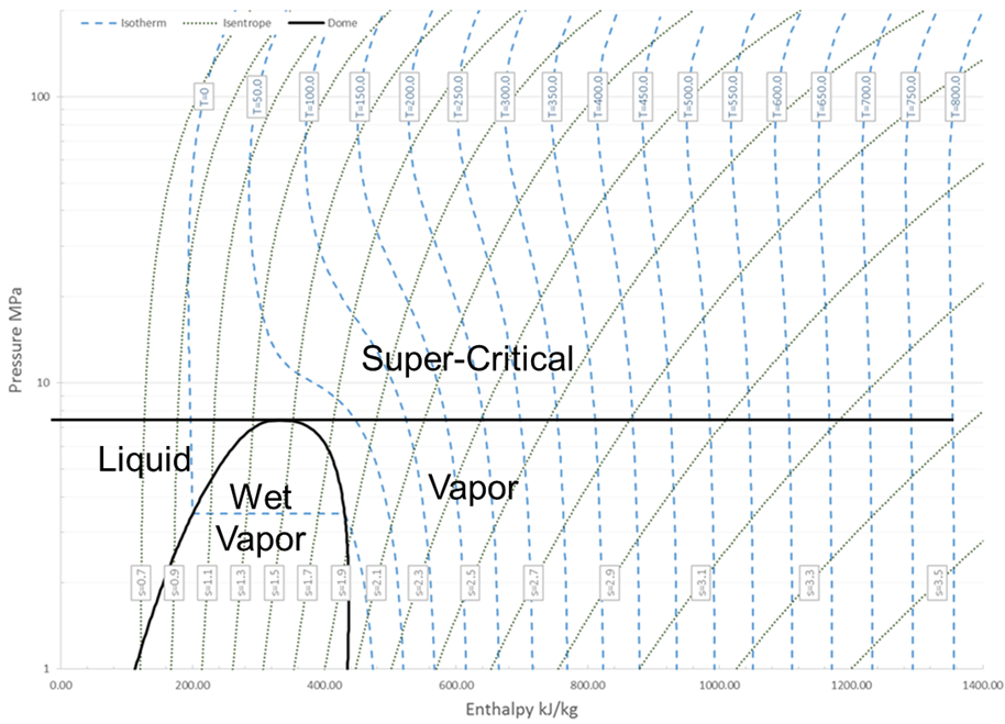
Figure 1: Carbon dioxide phase diagram (Courtesy of Southwest Research Institute).
The promise of supercritical carbon dioxide (sCO2) Brayton cycle power systems has grown steadily over the past ten years. To understand the current status of these sytems, let’s start with some of the basics.
Carbon dioxide (CO2) is chemically stable, reliable, plentiful, low-cost, non-toxic, non-flammable, and readily available. This qualifies it as a safe working fluid for a closed cycle. Raising CO2 to be at or above its critical temperature and critical pressure puts the fluid in a supercritical fluid state (Figure 1). sCO2 occurs at a relatively low pressure as compared to other gases, allowing for a high-density, low viscosity, and compressible fluid. When sCO2 is applied to a closed-loop Brayton cycle, this allows for increased efficiency of the resulting power cycle and high power density (substantially smaller footprint both physically and environmentally) as compared to air Brayton and steam Rankine cycles.
Closed-loop Brayton cycles using CO2 in the supercritical fluid state are not a new concept. The Sulzer brothers patented a partial condensation CO2 Brayton cycle in 1948. But the challenge in implementing those cycles at commercial scale has meant a long development history. Solutions are now on the cusp of market entry.
Figure 2: A recuperated sCO2 Brayton cycle gives good performance for a reasonable cost.
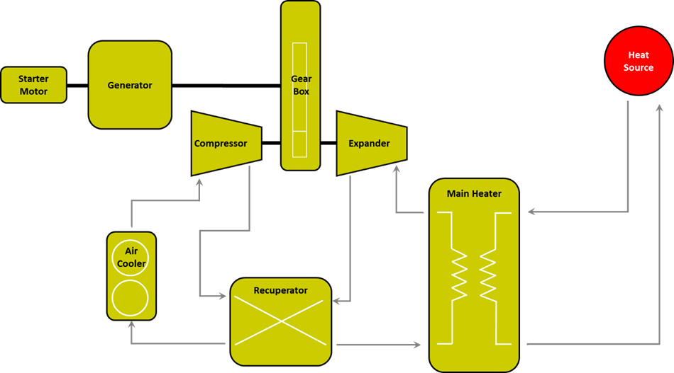
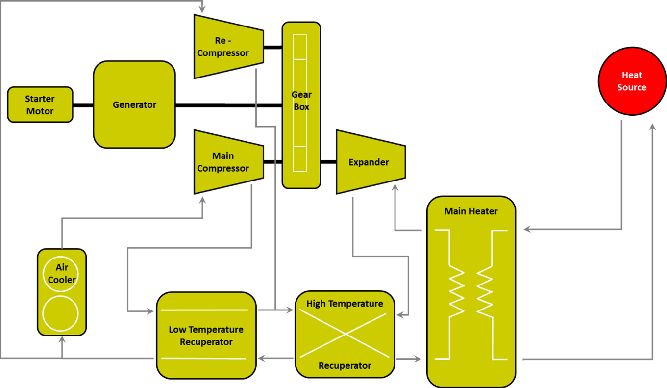
Figure 3: A recompression sCO2 Brayton cycle gives the highest performance but it comes at a premium for total installed cost.
TRADE-OFFS
There are a number of cycle variations associated with the closed-loop Brayton cycle that balance technologies, costs, and efficiency. Cycles pulling flow after the turbine to reheat it before reinjecting it into another turbine stage are called reheat cycles. However, the modest performance gain with reheating between turbine stages does not always provide sufficient gain in cycle performance for the added complexity and cost.
The two most prominent configurations are recuperated and recompression cycles (Figure 2 and 3). A recuperated cycle allows a portion of the unused heat from the turbine to be captured via a heat exchanger, which can then heat the compressor gas discharge, thus reducing the overall required external heat input. The recompression Brayton cycle uses a high-temperature and a low-temperature recuperator. Flow is split prior to entering the precooler, recompressed, and passed through the high-temperature recuperator after being reunited with the rest of the flow that has been heated by the low temperature recuperator. The recompression system offers high thermal efficiency (upwards of 50% depending on temperatures) but is one of the more complex and costly configurations.
It is important to understand that sCO2 power cycles are heat-source agnostic. The heat may derive from any of several different sources: concentrated solar power, nuclear fission, waste heat from chemical processes, or recapturing the exhaust heat from a gas turbine (cogeneration).
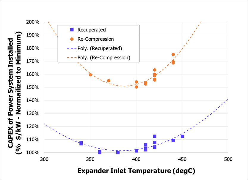
Figure 4: Relative installation cost ($/kW) based on various expander inlet temperatures.
Power systems deriving from sCO2 closed-loop Brayton cycles offer advantages over existing technologies that convert heat to electrical power. These include:
- Increased cycle efficiency (power generated divided by heat put into the cycle)
- Compact size: Power density means a reduced footprint compared to steam turbine plants or organic Rankine cycles, an advantage in applications where space is at a premium such as offshore platforms and ship propulsion. It also offers advantages in terms of the turbomachinery cost. The cycle may be optimized to achieve the best balance of power recovery for total installed cost (Figure 4.)
- The Brayton cycles are more efficient than steam and organic Rankine cycles at heat temperatures above 400°C. The resulting applications cover both fossil and renewable energy.
- By combining with gas turbine-produced power, greater power output per unit of fuel consumed is achieved.
Figure 5. Concentrated Solar Power (CSP) can take advantage of sCO2 to increase efficiency.
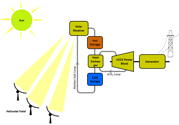
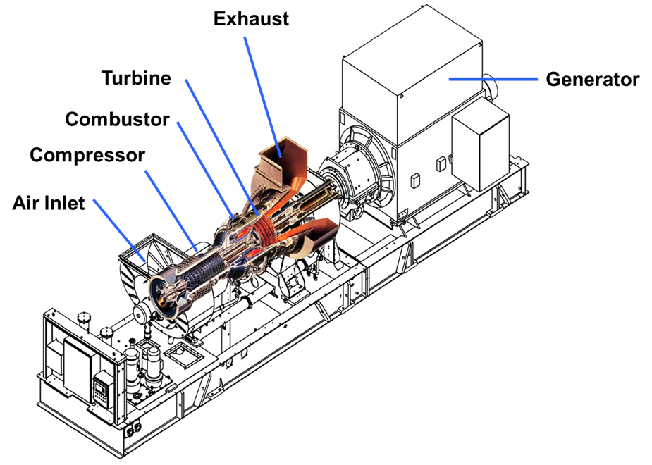
Figure 6: Heat recovery can be from exhaust of gas turbine or any industrial process producing sufficient discharge heat. (Courtesy of Solar Turbines Incorporated)
sCO2 DESIGN
Hanwha Power Systems chose to focus on power ranges in the 5 MW to 25 MW range and leverage existing industrial technologies within the company to the extent possible. Development effort centered on technologies that proved system function and maximized reliability, such as sealing and wide range compression technology. The result is an integrally geared compressor-expander arrangement for turbomachinery that uses additive-manufactured compressor impellers and expander wheels to achieve aerodynamic configurations. Applications in this power range are predominantly concentrated solar power (CSP) (Figure 5) and waste heat recovery (Figure 6).
Applying the design and operation of a high-power density system to an industrial market is challenging. It presents multiple technical barriers to market entry. One of the inherent risks associated with such high-density equipment is to over leverage the design on unproven technologies. This leaves little time to make corrections during tests and field trials.
Sandia National Labs established a 150kW sCO2 flow test loop to prove the efficacy of various cycles. Other national labs, research centers, and universities have similar test rigs for core research. At this scale, the turbomachinery operates at extremely high rotational speeds. Due to the small flow passages, it does not represent the component efficiencies achievable at larger scale. However, the cycle function is proven and paves the way for applying the lessons learned to larger machines.
Advances in analytical tools and manufacturing methods have opened the door to successfully applying sCO2 Brayton cycles and lowering dependency on unproven technologies. With solutions now at hand, the field is transitioning from academic and small-scale test rigs into the megawatt scale. The main challenges relate to proper understanding of the fluid properties, management of concurrent high-pressures and temperatures, and sealing against those conditions.
Understanding the thermodynamic properties of fluid properties in the supercritical regime requires substantial testing and validation work. The transient, start-up, and shut down sequences of the cycle must be managed carefully to control potential two-phase flow and fluid instabilities to avoid machinery damage.
Thermal management of conditions at 700°C may seem less challenging as compared to gas turbine temperatures exceeding 1200°C. But 700°C has to be managed concurrently with pressures of 250 bar or greater. Pressure containment favors thick-walled non-compliant systems to withstand mechanical stresses, whereas thermal management of mechanical systems is oriented toward structural compliance of parts to reduce thermal stresses.
One strategy is to make a closed system with no leakage. These canned systems eliminate sealing complications but add challenges with operating process flow bearings. Alternatively, conventional (rolling element or fluid film) bearing systems can be used. But then sealing systems must be applied to restrict gas leakage to atmosphere to manageable quantities. Due to high- pressure fluids, labyrinth and floating ring systems are insufficient. The use of dry gas seals is logical, but the pressures, surface speeds, and temperatures are just about at the limits of the capabilities of dry gas seals.
And there are other technical challenges. High pressures in turbomachinery components lead to high-thrust forces. Those forces can have a high degree of uncertainty due to variability in operational conditions and pressure fluctuations. In the case of heat exchangers, the exchangers must be efficient and able to handle quite high pressures (up to 280 bar) at not insignificant temperatures. Further, the selected materials must provide adequate strength and corrosion resistance at operating temperatures and pressures. Static sealing must be tolerant of CO2 and potentially rapid fluctuations.
OVERCOMING TECHNICAL CHALLENGES
Overcoming the concurrent technical barriers of high rotational speeds, fluid pressures, and operating temperatures requires dependence on analytical tools and advanced manufacturing practices. Advances in analytical tools and, importantly, the ability to anchor predictions on low power scaled test results from universities and national labs from around the world, proved essential to achieving recent successes.
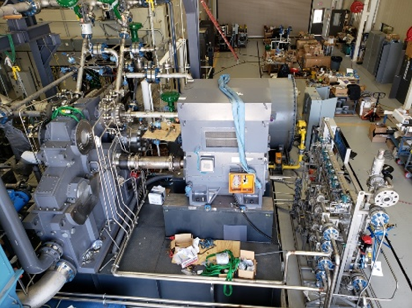
Figure 8: Integrally Geared sCO2 turbomachinery skid on test at Southwest Research Institute.
The preliminary compressor aerodynamic design was scaled and tested in air at Southwest Research Institute. Having this benchmark data allowed the design to be checked prior to testing in CO2. Compressor aerodynamics near the critical point of the fluid are challenging. The gas density flattens and small temperature and pressure changes create large swings in fluid density. This directly affects local velocity vectors. It also makes it difficult to accurately predict aerodynamic efficiency.
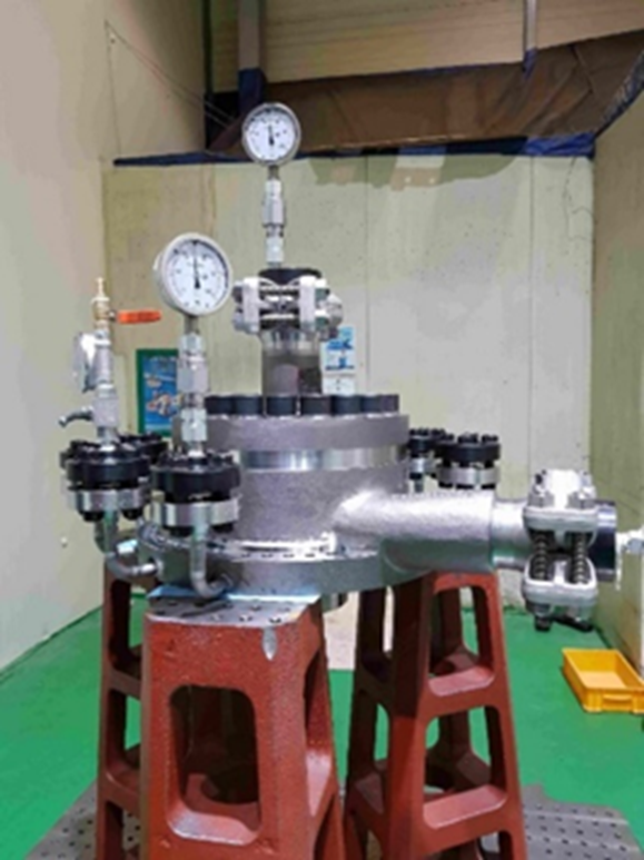
From a structural perspective, understanding the statics and dynamics of the fluid system is critical to avoiding fractures in the material during operation. A hydro test of the high-pressure compressor was carried out at 477 bar (6,918 psi), roughly equivalent to the pressure 2.9 miles below the ocean surface (Figure 7). With the use of finite element analysis techniques, the design succeeded in hydro test and subsequent aero-mechanical performance testing in sCO2 when cycling to holding at full pressure and temperature
A decade ago, dynamic simulations took weeks to converge. Nowadays, they take hours. This makes cycle and system layouts optimizable in short time frames. With the understanding of dynamic predictions of transient behavior, estimates are at hand of dynamic forces that the system must tolerate. Prediction of creep life and high-cycle fatigue can now progress in real time.
To overcome system level technical barriers on closed loop full scale cycles, greater than 1 MW, no options were available at existing test facilities.
Hanwha Power Systems, with the support of U.S. DOE funding and in collaboration with Southwest Research Institute, developed a 10 MW system and performed incremental section testing at the 1 MW scale, using only the highest temperature-pressure expander stage. Demonstrating the most challenging expander stage was taken as proof that the low pressure-lower temperature stages would be viable. This testing program (Figure 8) demonstrated mechanical, thermal, and aerodynamic capabilities of the expanders, compressors, gears, bearings, seals, and heat exchangers for operation in supercritical CO2 for pressures and temperatures up to 280 bar and 730°C.
Figure 7: The hydro-test of the high-pressure second stage compressor to prove its ability to withstand high operating pressures.
Demonstration testing of major cycle components enables development to move to the next step: full-scale testing in the field. DOE funding applied to part of this program was from the Concentrated Solar Power (CSO) APOLLO program (to reduce the levelized cost of electricity for CSP). The ongoing phase of technical readiness is a pilot field test of a 5 MW sCO2 closed loop power system scheduled for 2024.
Acknowledgement: The material is based upon work supported by the Department of Energy, Office of Energy Efficiency and Renewable Energy (EERE), under Award Number DE-0007114. ■
Dr. Karl Wygant is Chief Operating Officer of Hanwha Power Systems Americas, a company that is commercializing sCO2. For more information, visit www.hanwhapowersystems.com


.png&w=3840&q=75)

.png&w=3840&q=75)


.png&w=3840&q=75)


.png&w=3840&q=75)


